Were it not for this, I might have finished the VS today, since the remaining rivets are all squeezed and thus easier to set. I have more rivets on order (of multiple sizes, just to be sure), and meanwhile the progress on the rudder is also stalled (since the counterweight rib was the next thing to rivet, which also takes -3.5s) - I guess it's time for another round of priming to start riveting the horizontal stabilizer together.
Meanwhile, the inside rivets actually came out quite good (only 3 needed replacement, which has been amazingly easy to do since I got this tool), except for a few scratches on the primer from hitting it with the bucking bar:
Time lapse:
Total vertical stabilizer time: 58h Total vertical stabilizer rivets: 234
Now that I know a bit more about antennas (lots of thanks to Don from Delta Pop Aviation for the patience explaining a lot of it), I've decided that I don't want to add a whisker-type antenna to the vertical stabilizer (more on that later), which means the VS is ready to be finished!
Before taking any other steps, I studied the best place to attach the bonding strap (which bonds the VS to the rudder), and decided to install a nut plate for it close to one of the hinge brackets (about the same height as in the rudder):
I then clecoed the skin on and double-checked that everything looked right:
I started riveting in the order suggested by vans - with the middle nose rib, followed by the top rib forward of the front spar:
The conduit proved to be annoying, as it got in the way of holding a bucking bar against some of the holes (tungsten bucking bar to the rescue!):
I got so far as to do the bottom nose rib and rivet the front spar as far as the squeezer would go (but it was late so I didn't want to annoy the neighbors by bucking any more rivets) - more to come later!
Time lapse:
Total vertical stabilizer time: 54.2h Total vertical stabilizer rivets: 141
I finished preparing the rudder for closing down, which involved installing a nutplate on the spar for bonding, which I installed close to one of the attachment nutplates in order to take advantage of both its doubler and later the opening through the rolled leading edge (for the bonding strap):
Nut plates: smaller for bonding and larger for attachment
We then proceeded to applying the sealant and join the two skins. The sealant instructions look very very cryptic - dasher rod? ram rod? Luckily, I found this RV-12 blog which literally translates them to something understandable :) Sealant mixed and applied, we proceeded to rivet the two skins together while rolling the top skin up (no pictures of the process - we were too busy and messy to play with cameras - but it's in the time lapse):
Fully join rudder skins (including the bottom rib)
Weights on the trailing edge to hold the sealant and skins together
That also involved riveting the two skins together:
Pop rivets joining the two skins together
Time lapse:
If it appears that one part of the video is going faster than another, that's because it is - I accidentally recorded a full day of work in regular 1080p 30fps mode - I sped that up 8x, but that's still slower than the 2fps I usually record time lapse in.
Over the last few days, I finished the rudder skins, and am now ready to apply sealant and rivet them together:
Rudder skins ready to be attached to each other
To remove the blue vinyl only from the rows of rivets, we modified a soldering iron tip to be hemispherical (by sanding it down), and that did the trick of burning away lines of the vinyl without scratching the metal underneath:
Vinyl-removing soldering-iron tip
After removing the vinyl strips, I started back riveting the skins, and found two issues - first, the rivets seemed to be too short (the shop head was below tolerance); also, most of them had one side (the side closest to the stiffener) improperly set:
Bad, bad rivets. No donut for you.
The bad corner turned out to be because of the back riveting set I was using (from ATS), which has a very large plastic piece around the actual setting surface - I solved this by getting one from Cleaveland, which has a much smaller protection (on the down side, it's harder to ensure you're at a right angle to the surface with the new one):
ATS (right) vs Cleaveland (left) back riveting sets
The short rivets appear to be because I'm using the substructure dimple die, so the dimple is actually higher. Changing the AD3-3 for AD3-3.5 rivets gave me just enough length to make proper shop heads.
Just enough of the rivet sticking out, if I use a half-size larger than indicated
I then set all the back rivets on the left skin's stiffeners:
Riveted stiffeners!
And then used a platenut drill jig and installed the nut plates for the static wicks:
Static wicks installed
And finally, installed the static wicks themselves:
Full rudder skin with riveted stiffeners and static wicks
The right skin followed pretty much the same procedure (minus the static wicks):
Marked regions of vinyl to remove
Clean vinyl cut
Installed stiffeners and shear clips on right skin
On the right skin, also installed the shear clips and the horn:
Installed shear clips
Shear clip, installed with LP4-3 pop rivets
Installing the horn was quite trivial using the squeezer - that is, until I got to the very last rivet:
No room!
There's just no room to use the squeezer (even the thin-nosed one). I tried (with my wife helping lift the other side a bit, and the result was a cracked shop head:
Cracked rivet head
At this point I gave up, removed the rivet with the cracked head, and installed a cherrymax (same one that's recommended for use later, on the other side):
Screw it, I used a CherryMax instead
The next steps are a little annoying to execute in that they involve sealant along the trailing edge (and all have to be performed during the 2 hours before the sealant stiffens).
Time lapse:
Total rudder time: 37.3h Total rudder rivets: 199 / 402
With the increasing number of bench-attached tools in the workshop, I realized we'd need more benches. We bought wood and hardware and built 2 more using the same EAA project (which is really easy to build), again just adding casters to make them easier to move around.
The result is much more actual workspace, where I can leave the bench tools attached and use the two new benches for assembly:
With only a few unprimed parts from the rudder, we spent most of Friday priming parts, including all the smaller remaining parts of the rudder (2 tabs, the horn and 3 stiffeners), both rudder skins and both horizontal stabilizer skins.
For the horizontal stabilizer skins, I used my super-advanced method to keep the markings after the PreKote etching - that is, taking pictures then re-marking before applying the primer. The marks were still visible through the primer.
Markings before priming
Faint marking after priming
Now after the primer cures I'll go back to riveting the rudder, including installing the static wicks.
Time lapse:
Total rudder time: 24.6h Total horizontal stabilizer time: 69.7h
I had a few coworkers who are also builders review my riveting work so far, and that led me to make some fixes - mostly squeezing a bit more on a few undersqueezed rivets, replacing one rivet, and to be more careful with edge deburring in the future.
I mounted the conduit mod by using RTV black glue on the top attachment and fastening the conduit:
Conduit attachment to rib
Conduit attachment (bottom)
Conduit attachment (top)
Rivet that had to be replaced (cracked head)
This time I used a different squeezer, borrowed from a coworker, and it made all the difference - I'm definitely ordering one of these for myself:
The Main Squeeze
I also realized that I have one more missing detail before I can rivet the VS skins - I need to attach a VOR antenna to the top of the VS (the conduit will be helpful after all), so I'm researching antennas (post on that later) and will finish the assembly after that.
We dimpled all the rudder parts which were already primed:
I'm not Santa, but I had a little helper
Lots of dimpled parts
Riveted rudder rib
Spar nut plate for attaching rudder to vertical stabilizer
Before I could continue the rudder assembly, I needed to prime a few remaining parts (3 stiffeners, the side of the other spar doubler and the rudder horn) - another post will cover the priming.
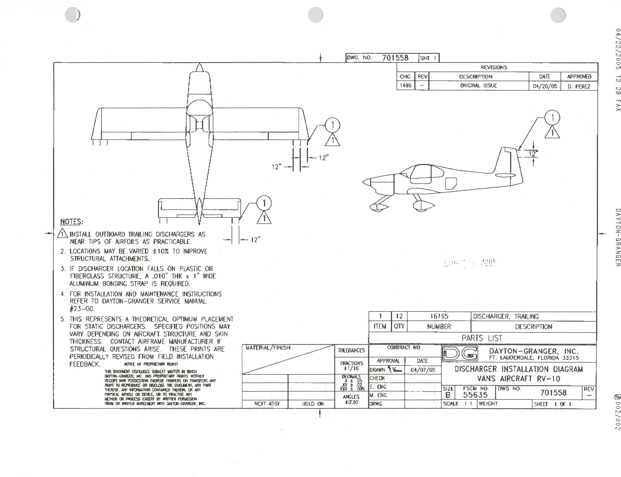
Since I do plan to fly my RV10 under IMC, I decided to have static wicks installed, specially after hearing multiple reports of PFD "white-outs" on planes without them (apparently the LCDs we use are very sensitive to static charge and eventually just stop working).
I started my research by looking at what other builders did, and found the very useful post by Mouser and another similar one by Tim Olson. Both of them used Dayton-Granger 16165, which sounds like a safe bet since Dayton-Granger themselves provide proposed installation instructions specific to the RV10. As much as it would be fun to remember Maxwell's equations to do the electromagnetic calculations myself, I thought I'd trust a company that does this as part of their business :)
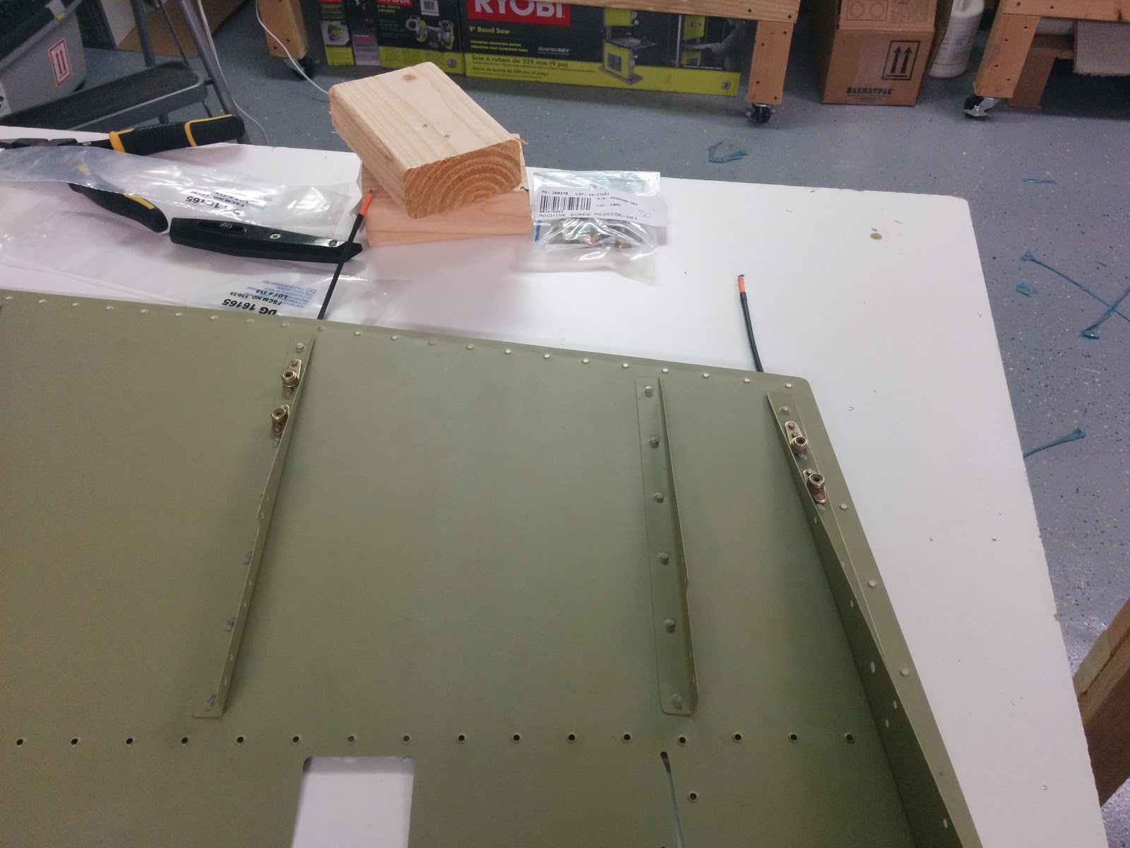
I'm going to follow Mouser's suggested bill of materials, so I ordered the parts for the rudder and elevators:
The next step is to make sure the electric charge can flow all the way to the wicks. Since I'm priming the parts, the surfaces are not conductive, so I measured the resistance of the skin from distant rivets on and got good results (1-2 ohms). For inter-part conductivity, I mounted one of the rudder attach bolts to the VS and saw that it's a poor conductor, meaning I need to do additional bonding there. The standard way to do bonding is with a braided strap. I also looked at pre-assembled straps with holes (such as this, this, this, this and this), but found that most come in inconvenient lengths and/or hole sizes, so I ended up ordering the braid plus 33457 terminals from Aircraft Spruce.
To attach the bonding strap to the parts, I'll add a nut plate to both parts (e.g. rudder and vertical stabilizer), for which I picked the same AN366F-1032A nut plate and MS35207-261 screws. The FAA AMT Airframe handbook (chapter 9, figure 9-146) shows the recommended sequence of washers, nuts and their materials for the case where you can install a screw + nut on the same side (but not for using a nut plate). Some more searching found me the Australian AC 21-99 which happens to have that same figure/table (not sure which government copied from which), but also has the equivalent for nut plates (chapter 13, figure/table 13-2):
Since the braided strap is tinned copper and the structure is aluminum, this gave me (for each bonding / hole pair):
2 MS35207-261 screws (cadmium-plated steel, same as for the static wicks)
2 MS35338-43 lockwashers (cadmium-plated steel) - options where the MS35338 or the MS35335, but since the Australian document mentions the MS35338 several times, I picked that
2 AN960JD10L / NAS1149D0332J washers (aluminum, for washer B). The FAA AMT book mentions the AN960JD10L as a suggestion, and I was tempted to replace these by AN960PD10L available at Spruce, but a quick look at the coating codes shows that J is MIL-C-5541 class 3 and P is MIL-C-5541 class 1A - according to the MIL-C-5541 standard, class 3 is really what I want ("where lower electrical resistance is required")
Today I set most rivets on the vertical stabilizer skeleton:
Vertical stabilizer skeleton riveted (except for bottom ribs)
Conduit for running wires up the stabilizer
Being my first big riveting job, it took some trial and error - for instance, I put all the clecos in, then realized that the rivets wouldn't go into the holes (tiny misalignment) - removing the clecos, putting some rivets (without setting them), and then putting the clecos back worked perfectly with no misalignment. Also, I tried to use my mighty pneumatic rivet squeezer, then realized (and forums confirmed) that the AD4-7 rivets I was trying to squeeze are too long for it - it only has maximum force at the last bit of its travel, and with a long rivet it just never gets there. I ended up setting most rivets with the hand squeezer, and only using back riveting for the rivets closest to the hinge brackets (where the squeezer doesn't fit).
I also realized that I need a better rivet squeezer - preferably lighter and that can access tighter areas such as the junctions of ribs and spars - those were more challenging than they should have been. I'm considering the Main Squeeze.
Other than that, the skin is fully dimpled, and as soon as I finish securing the conduit (need to buy supplies for that) I can start riveting the skeleton to it.
I also broke my big toe on Friday, so the next few sessions will be slow at best.


 Now that I know a bit more about antennas (lots of thanks to Don from


 I finished preparing the rudder for closing down, which involved installing a nutplate on the spar for bonding, which I installed close to one of the attachment nutplates in order to take advantage of both its doubler and later the opening through the rolled leading edge (for the bonding strap):