I received my engraved Tosten sticks from Midwest, and they look great! (I had asked for a low-dome blue button for TOGA, but oh well, this is good enough)
Engraved Tosten stick, aft side
Engraved Tosten stick, forward side
I installed the knobs and switch on the overhead face plate that Stein made, which required a few tweaks - the heatsink on their provided dimmers didn't fit, so it had to be slightly bent:
Switch pod with knobs and switch installed
Inside the switch pod, heat sinks had to be slightly bent near the bottom
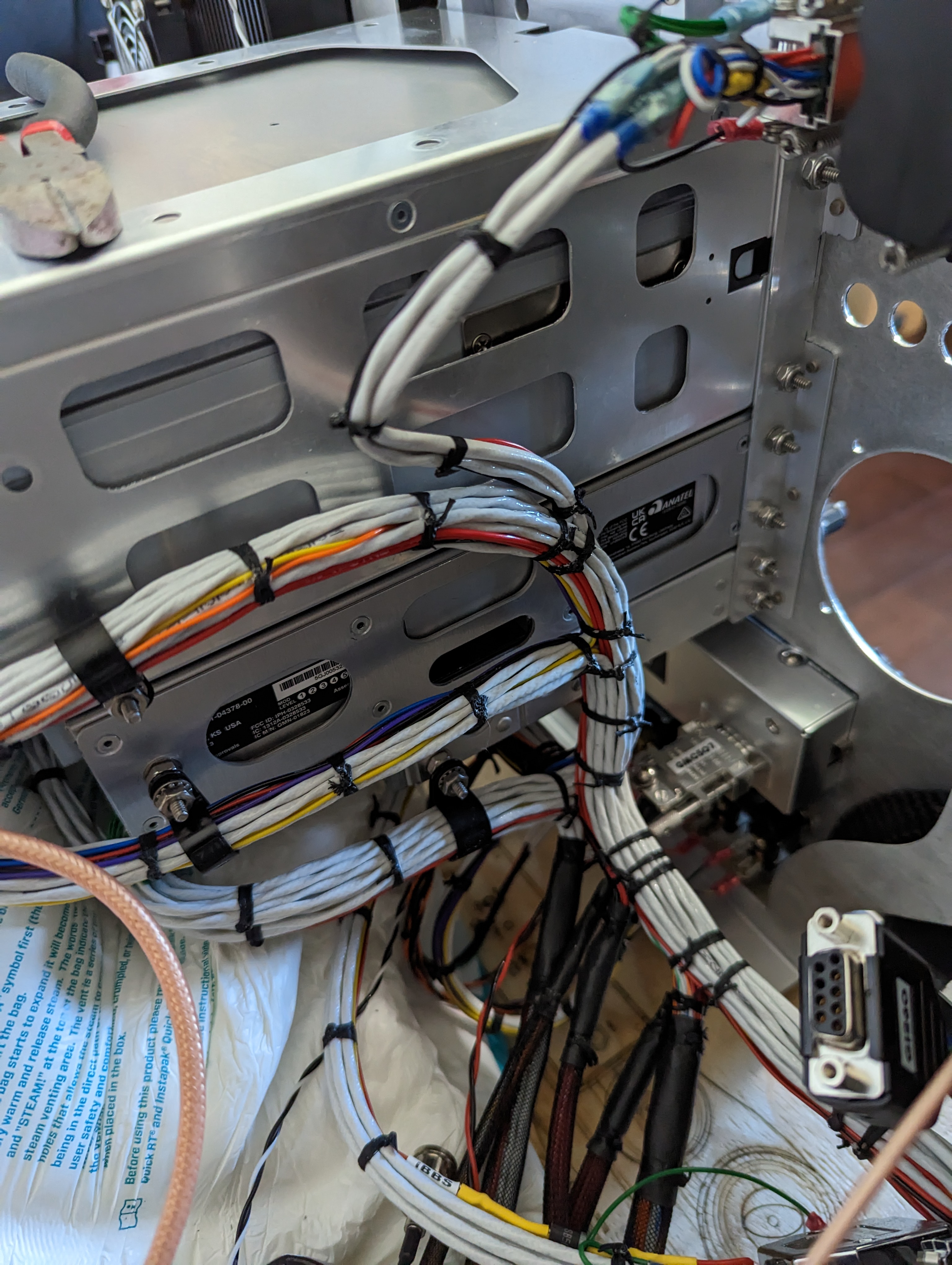
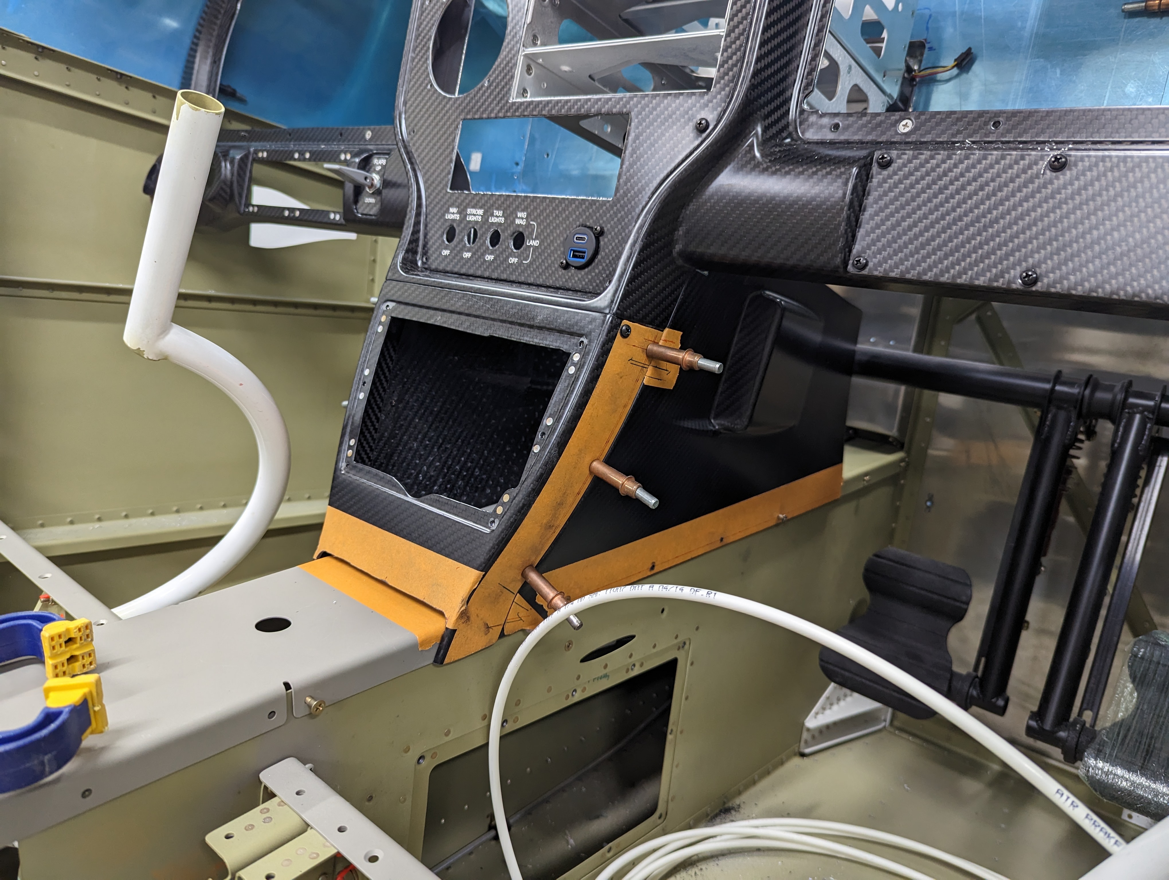
It was then time to attach the LRUs to the subpanel - starting with actually mounting the whole panel and getting the wire bundle in there (who knew, that wire bundle is quite heavy!):
Wire bundle installed in place (pilot side)
Wire bundle installed in place (copilot side)
GDL51R, fuse block, GAD29, and REL2 (left to right) attached to the subpanel
For the CO Guardian, the bracket it comes with seemed very flimsy to me, so I cut some aluminum angle to support it and attached it facing down (so dust doesn't get into the sensor as easily), and away from the G3X and panel-top cooling fans:
Custom aluminum-angle bracket for the CO Guardian
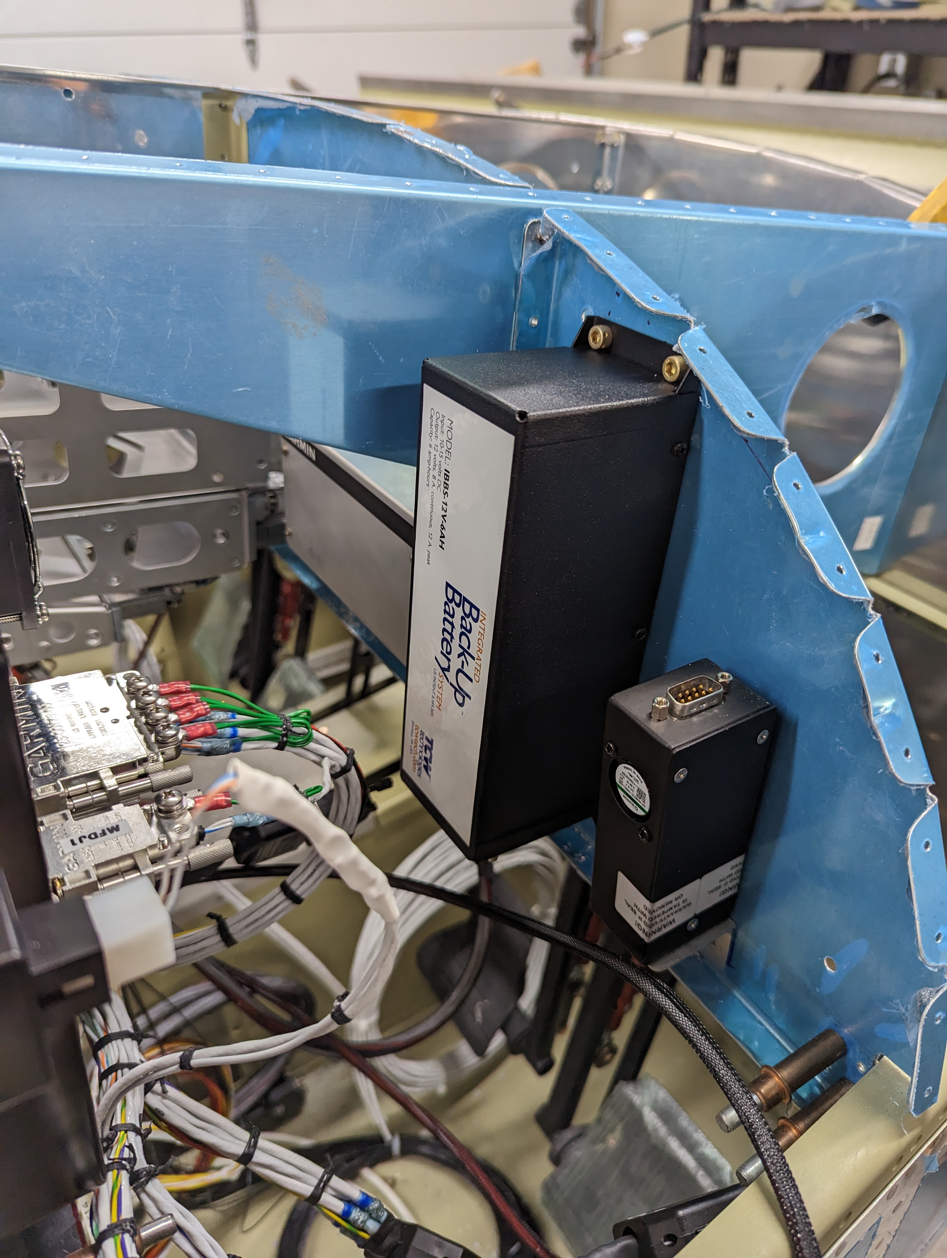
CO Guardian, IBBS backup battery, and GEA24 (right to left) attached to the subpanel
Last, I connected the GSU25 and G5 air pressure fittings and ran the tubes between them, then ran the static tubing down to the alt static switch, with a T to actually receive the pressure from the static ports:
Pitot and static hoses between GSU25 and G5
Static hose routing down from G5 to alt static switch, and a T for the actual intake
Static hose coming from from G5
There's still a chance I may need to change the static hose out of the G5 - I don't have the EFII display yet to know if it'll be a conflict, and I routed as far away from it as I could, but there's always the chance it wasn't enough.
Last but not least, I final-drilled for and installed the ELT antenna:
ELT antenna installed in place
Next I need to figure out the mounting of the VP-X (thinking of going with the hinge method on the pilot side), adding Adel clamps to hold the main wire bundle, and then the actual modifications to the bundles (like running the wires that Stein doesn't, and a few other minor changes).
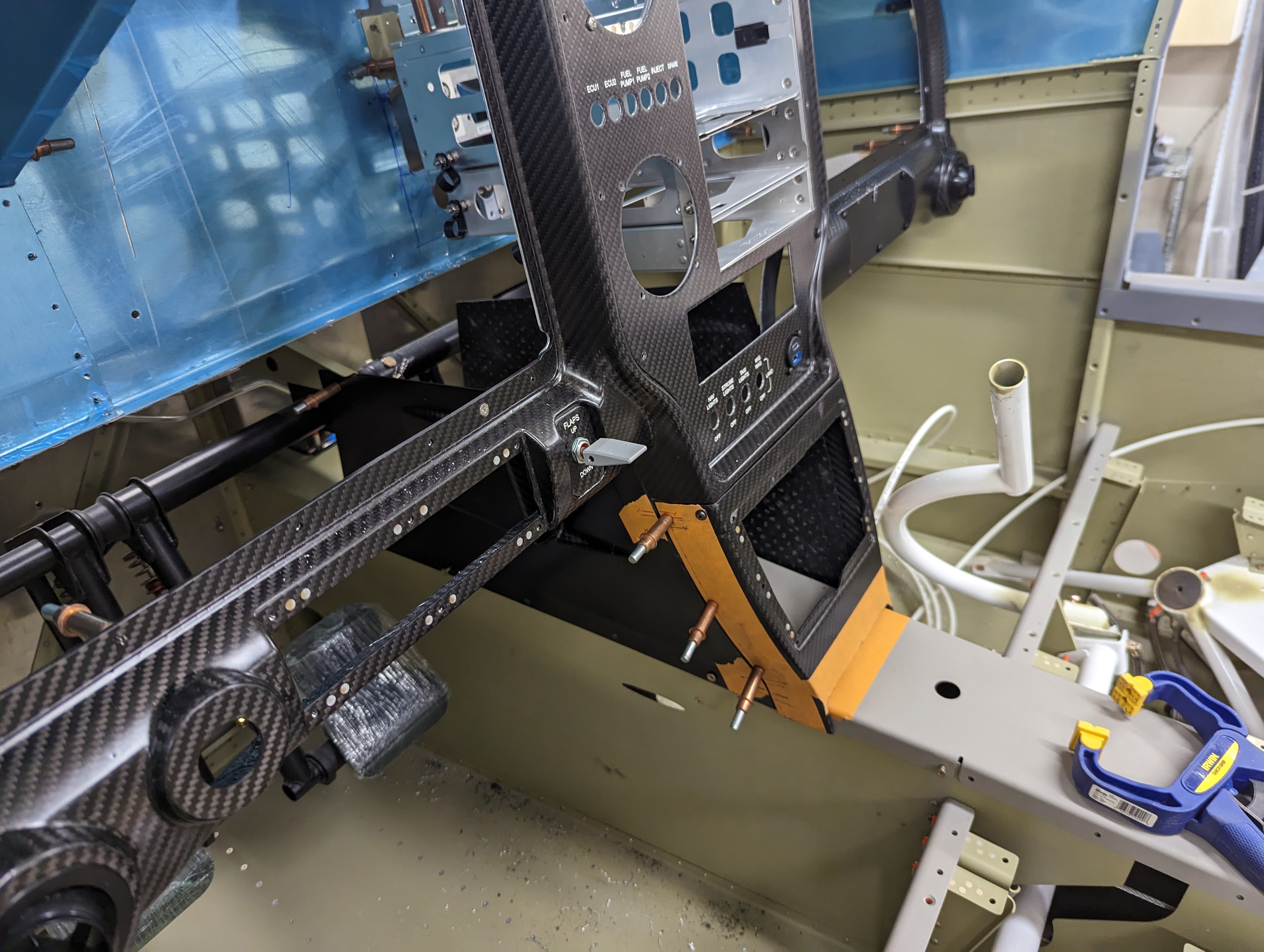
I mounted the panel on the plane, and realized the GTN rack didn't fit - so like many before me, I had to trim that center rib (though much less than I have seen others do):
Center panel in place (minus the GTN rack which doesn't fit)
GTN rack fits after trimming center rib
Complete center panel in place
Also, since the GTN and GNX were so close to the subpanel, I had to open it up for the connectors and fan to go through (a doubler will be added later):
Subpanel with holes for GTN/GNX connectors, and trimmed rib
GTN backing plate through the subpanel hole
The GNX holes were a bit too low and required adjustment, but the were fine on the second attempt:
GNX backing plate viewed through the subpanel hole
To keep the racks from vibrating, I also attached the back fo the GTN rack to the center rib (which also serves to reinforce the part of the rib that I removed):
Aluminum angle (top left) attaching the top of the GTN rack to the trimmed rib
I also measured and, to make it ever simpler, there's enough of a gap between the GTN itself and the inside of the rack (0.095"), that I don't need to dimple those holes upward and use countersunk rivets - the shop heads will fit just fine.
Finally, the wire bundle that Stein made was not long enough to go around the bottom as I had hoped :/ so I had to further enlarge that opening to let the wires through the original route:
Original SteinAir routing for the GTN/GNX/GMA
Enlarged opening for the GTN and GNX bundles to go through (black part is just temporary rubber edge protection so the wires can rest on the unfinished edge)
Next I'm going to attach all the LRUs (I'm making a separate post about the rest of the avionics install, and keeping the section41 tag only for the structural modifications), and then will come back to this section, make doublers, and rivet everything.
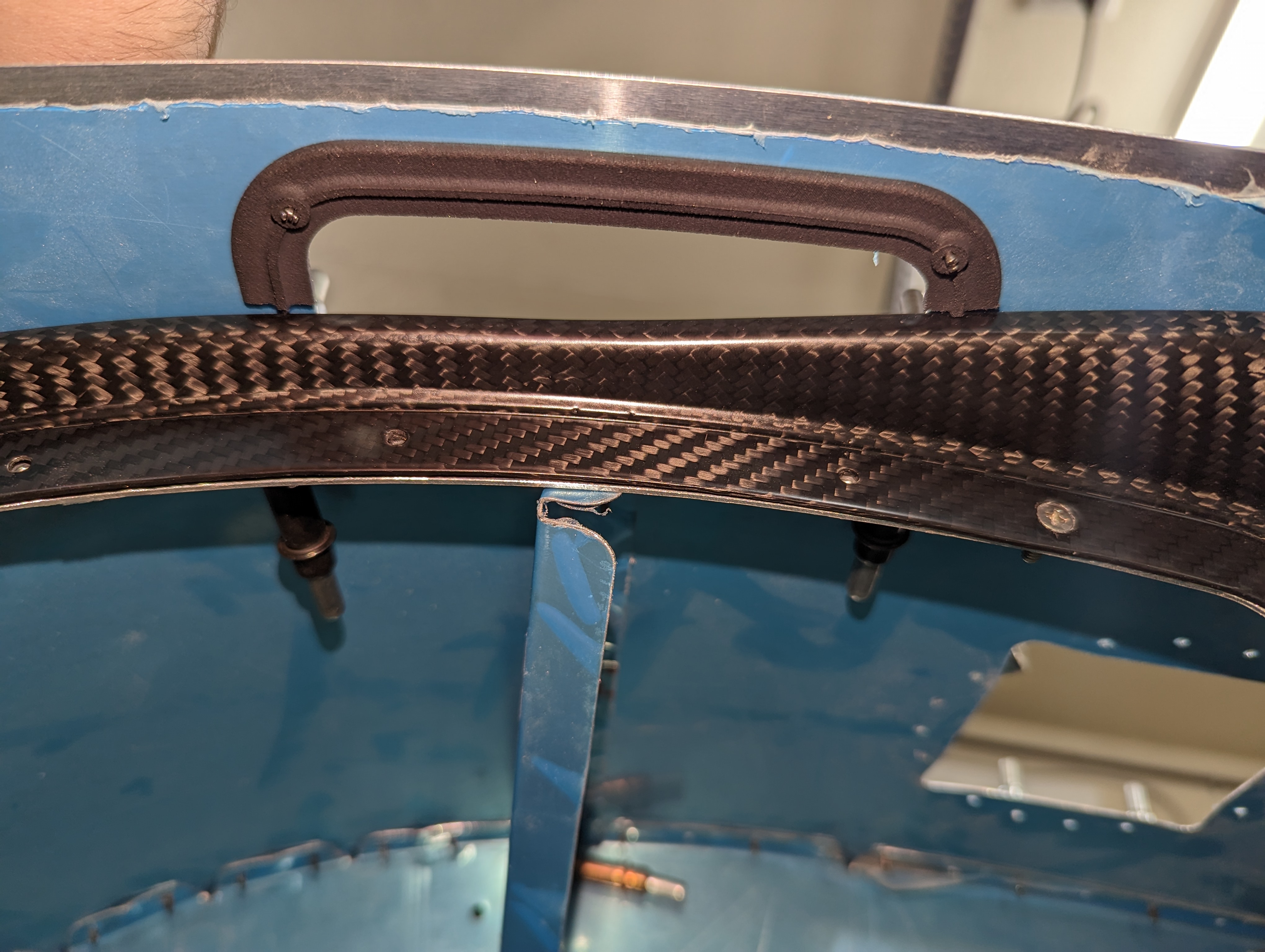
I continued work on the panel by attaching more of the Aerosport parts, starting with the handhold guards - these are straightforward 3D printed parts, though they did require some trimming to make the stock handhold doubler fit within its edge (to the point that one of the rivets will have to go on the skin underneath only):
Hand hold cover clecoed in place
Bottom support for the hand hold cover, trimmed to not hit the panel
Hand hold doubler trimmed to fit inside the hand hold cover
Finished hand hold doublers and covers
It was then time to attach the bottom side panels - aligning them took a few attempts, since the ideal position that makes them fit flush where they curve also made them too high to attach to the tunnel cover - so I lined up with the tunnel cover instead, and likely nobody will ever notice the small offset around the curve (minor annoyance - there's no such thing as a #19 strap duplicator! Had to use a #21 then final-drill):
Bottom side panels match-drilled in place
Multiple attempts at marking heights for the side panels
Side panels attached in place
With the side panels attached, the panel was finally stiff and the bottom center panel had a definite position, which allowed me to get started on the center armrest console. I started by making the hole and slot for the throttle quadrant adjustment knob (that adjusts how stiff the quadrant is):
Open slot for throttle quadrant adjustment in center armrest
I then proceeded to align the armrest right up against the center bottom panel and flush with the tunnel covers, and match-drill it with a strap duplicator:
Armrest console attached in place
I left a few holes out from the armrest - notably the holes that were right next to other holes, the 4 aft holes on the second (third since I split the first) section of the tunnel cover, and one more up front. These were dimpled so I can secure the tunnel covers before the armrest is attached, and helped keep the tunnel covers in the right position for match-drilling:
Tunnel cover with some dimpled holes for securing underneath the armrest console
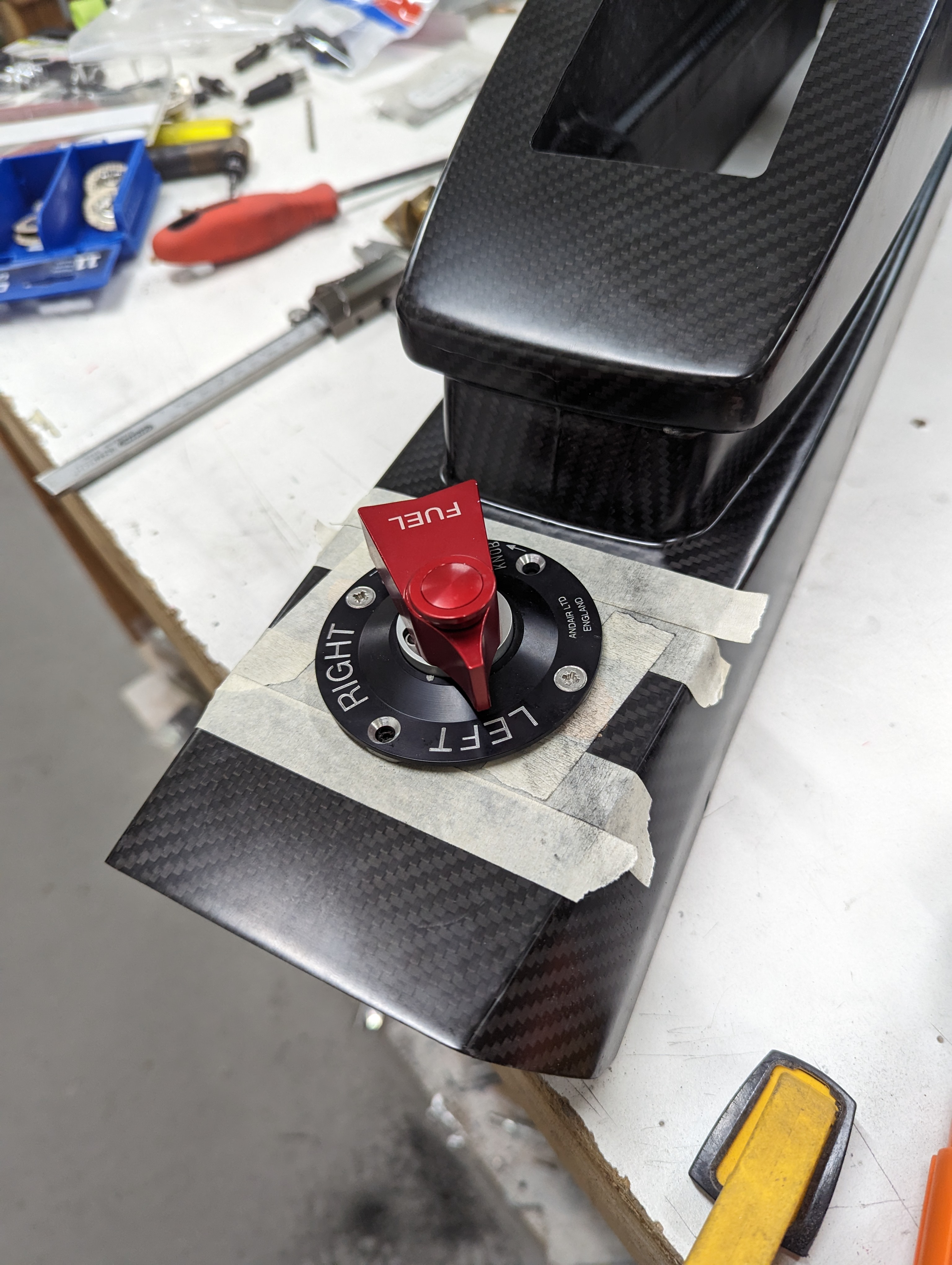
Finally, I worked on the fuel selector - first by marking and drilling a 1/2" hole through the tunnel cover opening (per Ed Kranz video), then initially trimming the valve extension flush with the armrest and enlarging the hole to 7/8", which let me attach the valve lever in place and measure more precisely how much more I had to trim the extension:
Fuel valve extension hole, with extension trimmed flush to the surface
Fuel valve lever attached to extension through armrest hole (still a little proud)
I trimmed the extension to the final length, then with the valve lever flush against the armrest (and attached to the valve underneath, but with all parts of it still on top) I marked and match-drilled the screw holes for the cover plate:
Fuel valve lever cover plate holes being match-drilled into armrest
Final length of the fuel valve extension after trimming - 4.038"
Finally, I disassembled the lever and mounted it properly, with the supporting structure underneath the surface:
Fuel valve extension installed in place
Next will be the quadrant attachment and attaching nutplates to those side panels.


