Lots of wiring harness surgery...I kinda wish I hadn't paid Stein for hand lacing since I'm having to remove/redo so much of it...
To re-consolidate the VP-X wire bundles (move all wires that should go into the main bundle into it, and move all the wingtip wires out the side the same way), I had to de-pin the Molex 150L connector, which was quite annoying to do, at least with the pin that Stein provided:
Removing VP-X connector pin using SteinAir-provided pin tool
I then got the official Molex tool, and unsurprisingly, it easily removed the remaining pins - the tip was just slightly rounder than the one from Stein, which did the trick:
Molex MX150L pin removal tools - SteinAir-provided (white) and Molex official (black)
I also moved the stick grip and flap wires into the tunnel bundle for simplicity:
Tunnel wire bundle
(Also, did you know that Spruce sells heat shrink by the 4ft piece, and not by the foot? Guess who didn't realize it when ordering and will now have a ton of leftover heat shrink? 😄)
For the EFII's AFR sensor, I got the Spartan 3 which seems to be good in terms of firmware and sensor, but I wasn't happy with the connector they use for power and data (screwed-in wires, specifically a OSTTE100104) so I chose a Molex connector with the same pitch but with a latch (172287-2308), and redesigned the case to fit it:
Spartan 3 AFR controller in original box, without original connector (left) and replacement connector (right)
AFR box model with connector and board
Center section of the AFR box
I also tried a right-angle connector, but ultimately didn't see a reason to use that:
Right-angle connector version of the AFR box
I'll eventually 3D print that (probably PC+CF filament?).
I received my main battery cables from Aircraft Specialty, and they actually fit as intended (caveat that they use white wires and only color the heatshrink, but the terminations are really high quality which makes it worth it):
Box of wires from Aircraft Specialty
(mock) battery, contactors and external power port with wires near their intended spots
(mock) battery and contactors with wires near their intended spots
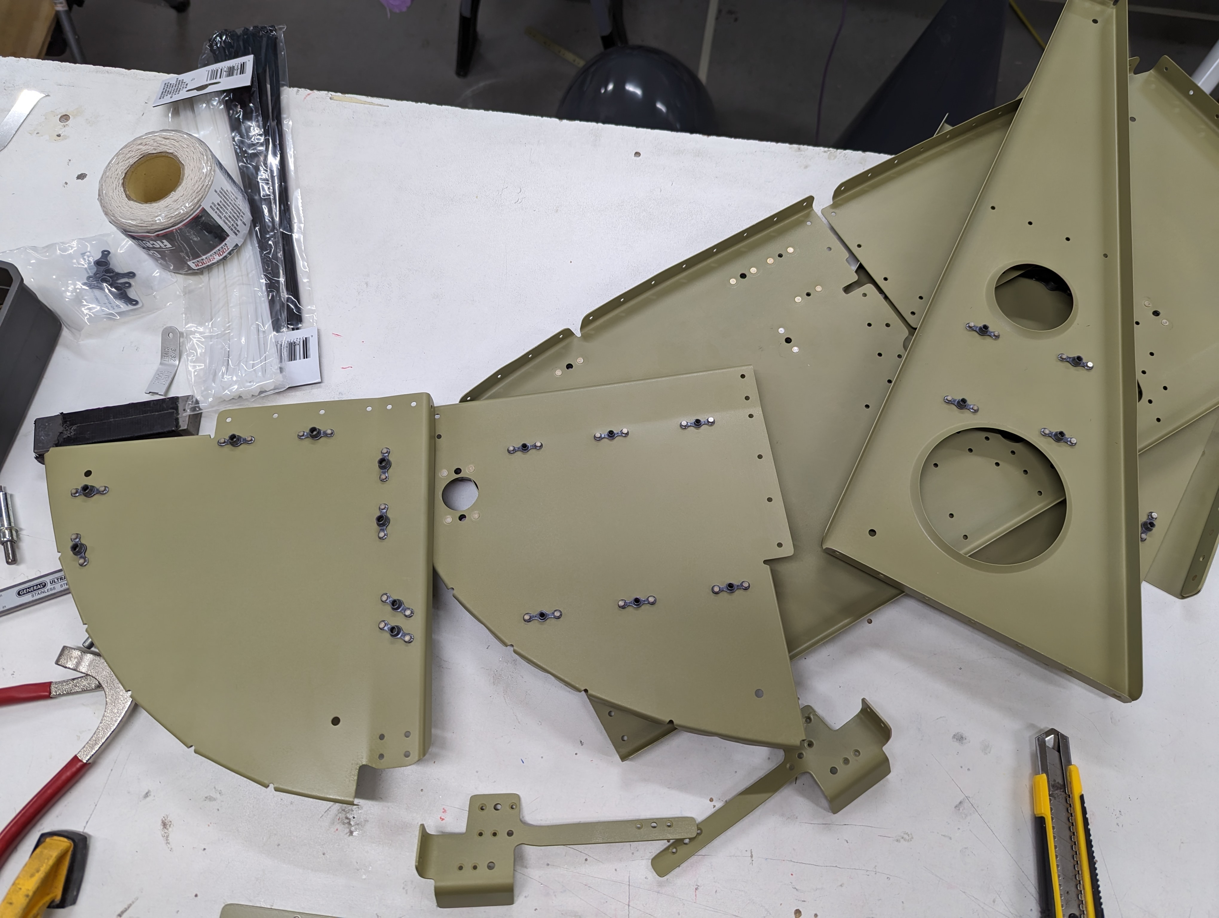
After a batch of primer, I riveted all the LRU attachment nutplates, to the tailcone avionics tray and the subpanel:
Tailcone avionics tray with LRU attachment nutplates
Subpanel parts with LRU attachment nutplates
I also riveted the VP-X attachment parts:
Riveted VP-X attachment hinge and bracket with nutplates
Coming up next: more wiring work, need to check/complete the GEA24 discrete inputs, rework the fuse block wires (I consolidated a few that go up to the overhead console, added the AFR sensor, etc.), connecting the trim position and ELT wires to the side breakpoint connectors, and simplify a lot of the O2 wiring (MH told me it's OK to run a single power wire to all the overhead distributors, so I'll do that instead of having 4 shielded sets).
I managed to measure the battery cable lengths I need, and those are on order from Aircraft Specialty. I also drilled nutplate holes for all the subpanel LRUs.
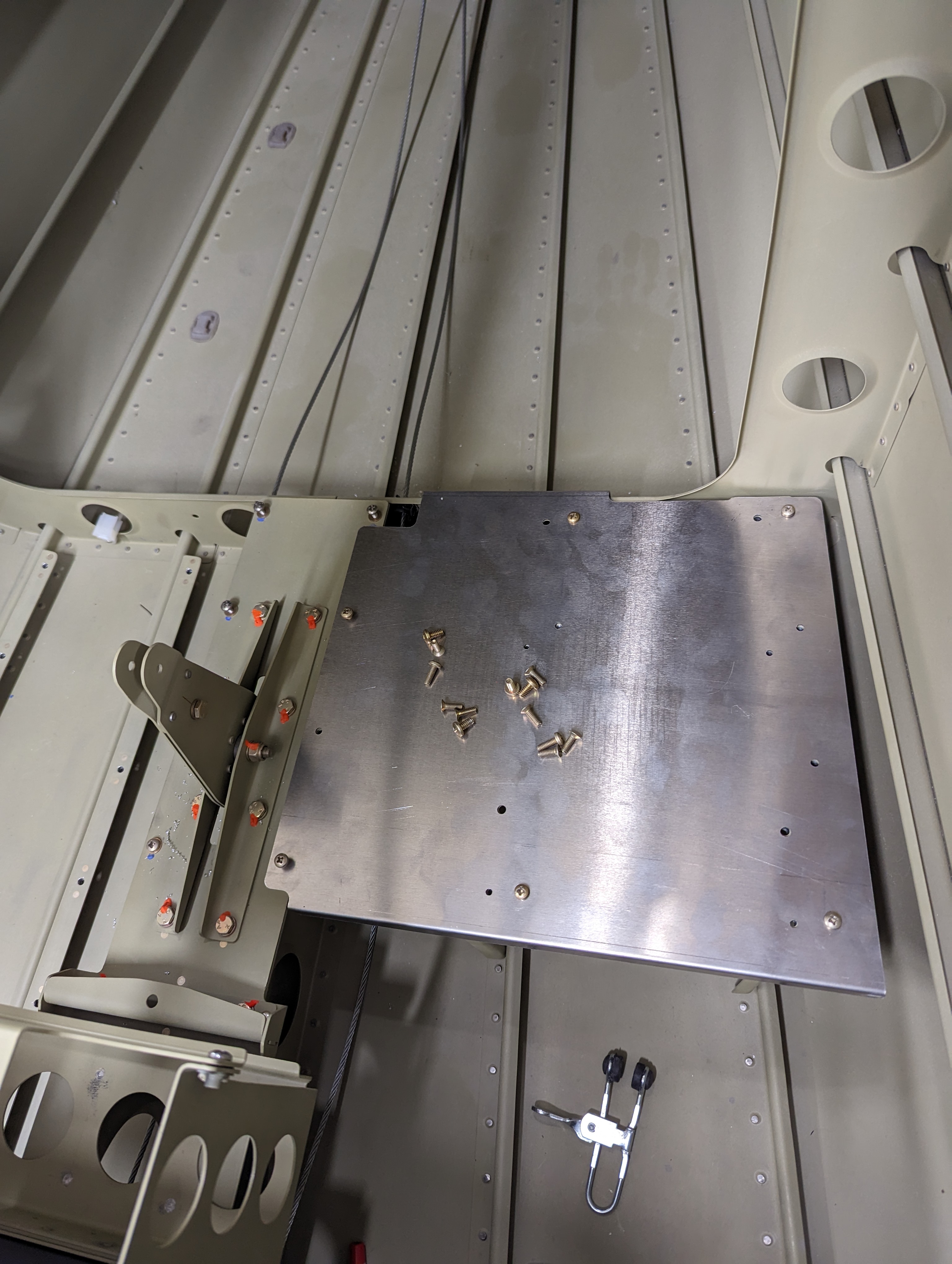
I fabricated the smaller tailcone avionics shelf (mentioned in the previous post) and drilled it for the GTS800 horizontal mount and the WX-500:
WX-500 (left) and GTS800 (right) mounts on the new tailcone avionics shelf
For the GTR20, I'm gonna have a modified version of the F-10112-R made to mount it on the side.
Stein had routed the stick wires to each side (adding splices near the LRU connectors), so I removed the splices and re-routed the wires to the center so I can have a single wire going down the center console and into the tunnel, where I'll install CPCs to attach the sticks. I'll later do the same for the flap wires.
Stick grip wires coming out of the ~center part of the harness
They also hadn't wired the GSB15 to the avionics dimmer bus, so I spliced the wire going to the PFD and added that connection:
PFD dimmer wire stripped at the center
Splice on the dimmer wire (not horrible for a first attempt)
GSB15 connector with dimmer wire
I also removed the WX-500 "display clear" and "COM inhibit" wires from the main wire bundle - I have no use for the display clear connection, and COM inhibit is only needed if I see interference from the COM radio (at which point I can just plug it back in).
Finally, I added Molex SL connectors to the reversionary switch and to the cowl flaps switch so I can remove the front panel without having to unscrew those from the panel:
Molex SL connector on the reversionary switch wires
Molex SL connector on cowl flap wires
I still have quite a bit more surgery to do to the wire harness. Specifically:
Add all the VP-X wires that need to go aft to the main harness
Move the taxi light wire from the VP-X J8 to the J10 connector so all lights are coming from the same side of the VP-X (easier to route)
Splice all the light wires so they can go out to both wings (and probably with the correct color wire, rather than all red)
Connect the door sensor wires
Connect the battery fault LEDs
Move flap motor and position wires into the center bundle
Redo most of the fuse block wiring
Move ELT wires into one of the breakout connectors (GTS?)
Add the wing root breakout connectors
Route the trim position wires into breakout connectors
I attached the two battery boxes together and to the bellcrank mount:
Battery boxes attached to each other
Battery boxes attached to each other with double-flush rivets, and to the bellcrank mount with flush rivets
Battery boxes attached in place with battery mockup
Battery boxes attached in place with battery mockup
For the contactors, I wanted to extend the OP-48 AHRS support bracket to span both ribs:
Original OP-48 shelf plus a paper extension for taking measurements
It took a bit of measurement and fine-tuning to get the holes in the right positions:
Sketch of the modeled shelf's web with measured hole positions
Rendering of the modeled shelf
Before sending this for fabrication, I 3D printed a thin version of it to confirm the layout:
3D printed shelf model
3D printed shelf model screwed in place
With just a few minor adjustments, I had the part laser-cut and CNC-bent in aluminum, and it fit pretty well:
Aluminum shelf screwed in place
Only exception was that the aft flange was too far aft (I tried to adjust both flanges slightly to not make the fit so tight as it was before, but clearly I adjusted too much, so I had to make a shim:
Shim for making aft flange of the shelf flush with the bulkhead
For connecting the 3 contactors (one for each battery and one for external power), I used a copper bar, which also held them in relative position for match-drilling the attachment holes into the shelf:
Copper bar with 5/16" holes for contactors
Contactors connected by copper bar, holding relative position
Contactors with attachment holes match-drilled in place
Last but not least, I cut a smaller right-side shelf for the GTS800 and WX500 (which I'll post about on my next avionics update).
Next on section 10 is just priming these parts, installing nutplates, and final-installing the relays and batteries in place.
I disassembled the subpanel structure and made a reinforcement doubler (just over 1" thick around the border) for the GTN/GNX subpanel openings - it will attach behind the subpanel, sharing a couple of holes with the subpanel angles that secure the center rib:
GTN/GNX subpanel cutout after finishing the edges
~1" doubler drawn out on sheet stock
Subpanel doubler cut out from stock
Subpanel doubler with pilot holes and bend to follow the subpanel contour
Subpanel doubler match-drilled in place
Opening up interior of the subpanel doubler by drilling out the corners
Finished subpanel doubler
With this, the subpanel is ready for primer, and I can start riveting the panel structure after that (though I'll leave the skin for later until I'm all done with the wiring harness).
Overall, I have to admit I regret doing the wingtip hinge modification - it added a lot of time to my build, and I'm not convinced it'll be that much more convenient since the pin is still quite hard to insert/remove due to the curvature.
I then drilled, countersunk and riveted the inspection panel and forward attachment nutplates:
Forward attachment and inspection panel nutplates riveted in place
Wingtip inspection panel screwed in place, with tinnerman washers
To ground the NAV antenna do the wingtip, I then scuffed the surface of the bottom left hinge, as well as inside the hinge rings, then riveted it in place:
NAV antenna and hinge riveted in place
Since the bottom left inboard hinge spacers don't need primer (they're helping ground the NAV antenna, I also riveted those:
Bottom left inboard hinge riveted in place
Finally, I glassed in parts of the NAV antenna to keep it held down:
Fiberglass strips holding the NAV antenna in place at 3 points
Now I'm really blocked on getting those ribs from Aveo - after a year talking to them to get those (well, trying, they're not great at returning calls or emails), I finally managed to place an order, so hopefully I'll get them some time next year along with my fixed light modules (that don't interfere with the GTN).
I installed a muffler/filter on the alt static switch to prevent dust from getting in:
Alt static switch (center) with filter mounted on it
I noticed some switches were rotating easily when manipulated, so I decided to actually use the anti-rotation retention ring and drilled notches (holes that don't go all the way through, so not visible from the front of the panel) and installed them all, as well as the circuit breakers:
Bottom left switches with anti-rotation washers in place
Left-side switches and notches for anti-rotation washers
Left panel with all switches mounted
Center panel with all switches and circuit breakers mounted
For attaching the VP-X, I went with the hinge method that lets it swing down if needed, and the #8 screw holes will double as a place to attach clamps to hole the main wire bundle:
VP-X attached with a hinge (left) and screw holes (right)
For flexibility/modularity and to make the routing of #2 battery and alternator/starter cables easier, I added an electrical post on the far left of the subpanel - from the aft side I can have thinner cables going to the VP-X and fuse block (the post will help keep those forward of the GDL that goes next to it), and another #2 from the forward side to the forward side of the firewall:
Forward side of the electrical post, where the firewall-forward 2AWG cable will connect to
Aft side of the electrical post, where the VP-X and fuse block will connect
Finally, I also drilled attachment holes for the two items that will go on the glareshield - one of the GPS antennas, and the GI-260 AoA indicator. The antenna unfortunately comes with the BNC connector already attached, so it required a much larger hole for the cable to go through than otherwise needed.
GI-260 AoA indicator attached to glareshield, and its cable hole
Garmin glareshield antenna attached to glareshield, with cable going through the glareshield
I also decided on the attachment locations for the tailcone LRUs - the GTS800 will be horizontal since it's pretty heavy, the WX-500 will be vertical next to it with connectors facing aft (to make routing to the antenna easier) and there's not enough room for the GTR20 on the shelf, so I'll mount it on the side with the OP-41 kit - both mounts have been ordered. I can also make the shelf smaller on all sides.
Rough layout of the tailcone LRUs
Next steps will be finishing that tailcone shelf and measuring/ordering the battery cables, then finishing up the subpanel (making the reinforcement for the GTN/GNX openings and drilling nutplate holes for everything), then actually making the wiring harness modifications I know I'll need or want.