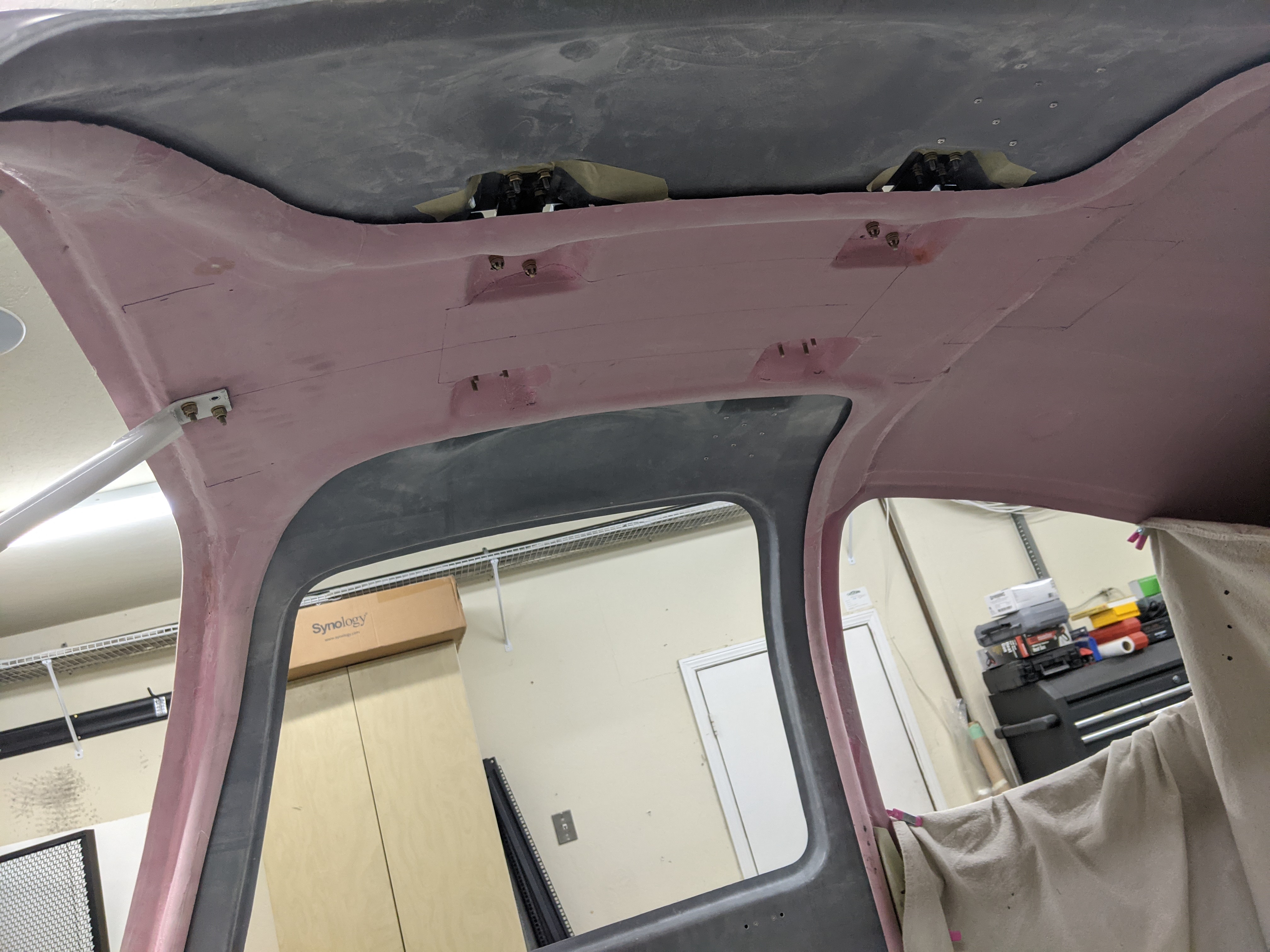
I started working on the cabin cover door flanges for the McMaster seal:
Cabin cover door flanges trimmed for McMaster seal
Cabin cover door flanges trimmed flush for seal
I had ordered a couple of different versions of the McMaster seal (just 10ft of each, the minimum they sell) to try out sizes, and it looks like the 1120A313 was the best fit, but I still need to adjust the gap from the door to be uniform before I confirm that:
Test-fitting the McMaster 1120A313 seal
Test-fitting the McMaster 1120A591 seal
I also took the opportunity to test fit the Airward reinforcement, and to my own surprise, the bolt holes were straight enough that it fit easily:
Bottom side of the Airward door reinforcement
Top side of the Airward door reinforcement
I then started the other door. I used the same technique, by cutting slots around the door to find the right depth (until the slanted part of the cabin cover shows), except this time I knew what to expect so I was much more aggressive in how much I removed, starting with the scribe line and going deeper in many of them:
Left door in place with "sighting" slots
Left door taped in place for drilling the hinges
Left door hinges attached to the door
After the doors were sanded to fit, there were only a few small flaws in the bonding of the door halves that will need to be filled:
"Air bubble" that was left when the doors were bonded
With this, after only about 40 hours of sanding, the hardest part of the doors (getting them to fit) is done!! Lots of finishing left, plus the latch mechanism, seal gaps, etc. Measuring the window heights on both sides, the difference was minor (about 0.1" in the front, 0.05" in the back), so I'm happy with the results.
We completed most of the control system assembly, starting with riveting and adjusting the pushrods:
Elevator pushrods riveted and adjusted for length
Safety wire to secure forward pushrod to control column
then installing the pushrods, control column and sticks:
Control column installed in place
Pushrods attached to elevator idler arm
Attaching sticks and pushrods
Sticks and pushrods installed
Finally, I was seeing some interference between the center pushrod and the tunnel hole, so I (at least temporarily) added some grommet edging to prevent having to touch up the primer there - if that turns out to be beyond the limits of the stick when everything is connected, I can easily remove it.
Center pushrod hitting the tunnel hole edge
Tunnel holes with grommet edging installed
With this, the only steps left from this section are to final-adjust the pushrod lengths (with the elevators actually connected) and torque the remaining bolts. Since I may still make changes to the battery mount (which houses the bellcrank), I'm leaving that for later.
With the last bit of section 26 out of the way, I completed section 40 by actually installing the flap motor. This required some trimming of the angles so the motor doesn't interfere with them when it moves:
PH flap motor brackets put together temporarily
A test run of the motor showed only minor adjustment needed to the rod end, and it was exciting to see something moving in the plane:
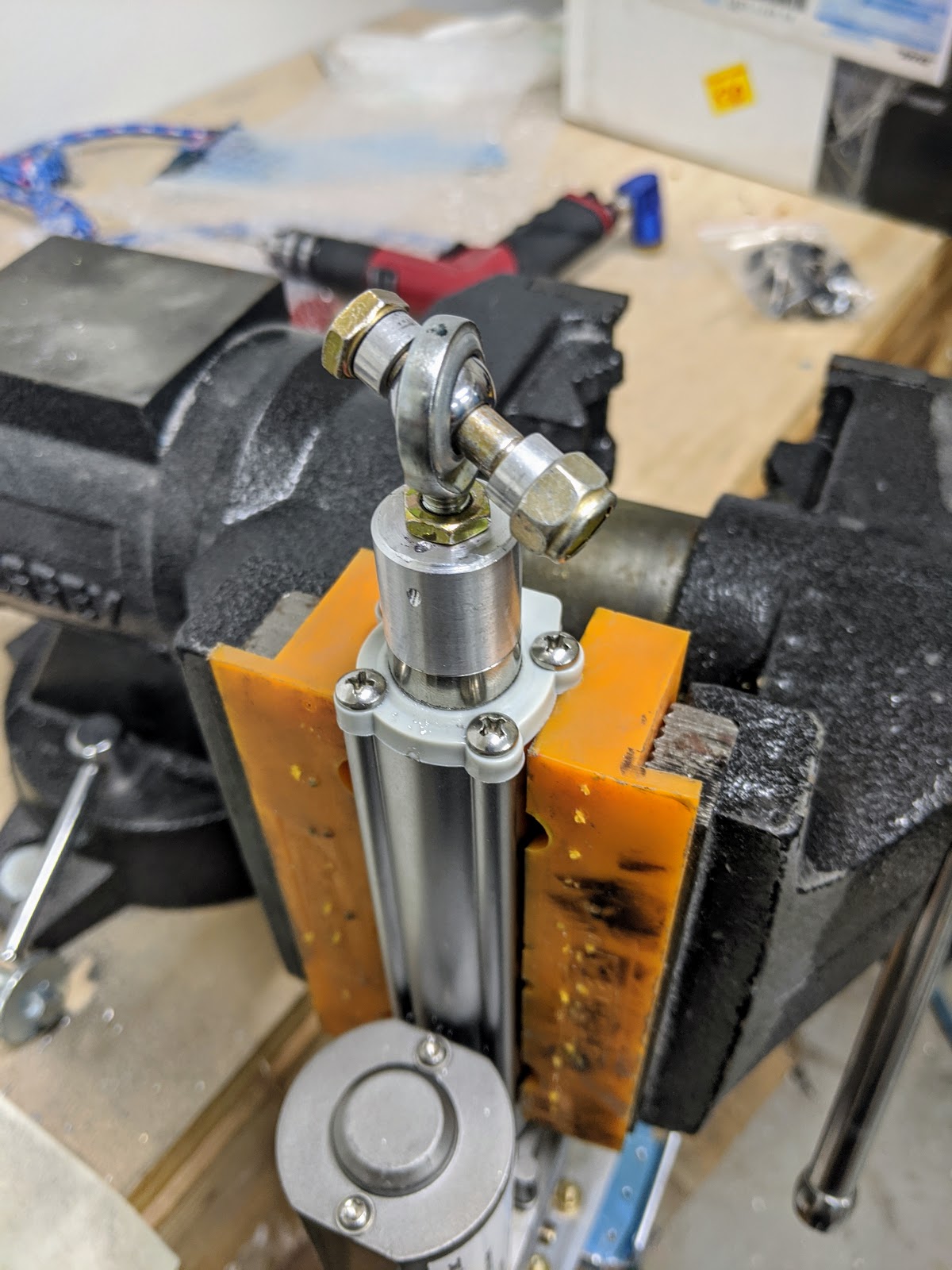
I made the spacers for attaching the motor rod end, and drilled the safety-wire hole at its tip (not strictly necessary since the tip doesn't try to rotate/disengage the bearing like the stock motor does, but it's added safety anyway):
Spacers for attaching motor rod end
Safety wire hole drilled through actuator head
Actuator head with attachment hardware
Finally, I picked the proper spacers from aluminumspacers.com for the motor - I ordered pairs of a few different sizes, but ended up using the 5/16" ID / 1/2" OD / 15/32" long ones:
Spacers for attaching motor
With this, I'm now going to sell the original flap motor (any takers?):
Stock vs PH flap motor
To actually install the flap motor, I also had to secure the TAS cable around it, which I started by running the cable to check its path:
Running TAS antenna cable near flap torque tube
TAS antenna cable running through tunnel around flap motor area
TAS antenna cable reaching antenna, with connectors in position
This was not good enough to understand the cable bends and overall path, so I actually crimped one of the connectors to it:
Stripped RG-400 for QMA connector
Crimped QMA connector
Inner QMA connector conductor, which needs to be soldered
Using that one cable (and the other 3 connectors) to see a realistic cable path, we installed the Clickbond fasteners along the cable's route, and checked that it won't interfere with the pushrod:
Clickbond fasteners installed in place for TAS antenna cables
TAS antenna cable temporarily secured to Clickbond fasteners around tunnel
TAS antenna cable temporarily secured and connected to antenna underneath pushrod
TAS antenna cable connected to antenna underneath pushrod
TAS antenna cable connected to antenna's far-end connector
TAS antenna cable secured to avoid flap crank
We were also wondering if it was ok to mount the control systems and flap motor at this time and still be able to install the antenna later, so we tried a mock install - turns out we can pass the cables out the hole, connect 3 of the 4 to the antenna and still get it back in place, with the last one being the only one that has to be connected through a tiny space around the flap motor and pushrod:
4 TAS antenna cables running through tunnel
Checking if the TAS antenna connectors can be secured from the outside
With this, after completing a large chunk of section 39, I finally installed the flap motor, mostly completing this section:
Flap motor installed in place
I'm leaving the final torquing of those last bolts, the safety wire and running the motor cable for later just in case I need to remove the motor to attach anything else in this busy section of the tunnel.