More elevator primer and riveting

I finally did the last batch of primer (or, it was supposed to be the last, at the time) - since it was a little cold, I had to use a tent (provided by my colleague Rick - thanks!! :) ) to set up a poor man's paint booth:
Paint tent set up
Inside the tent, all ready to prime
I made one more small mistake - I scuffed E-918 with PreKote, without realizing it's an exterior part. I got a replacement.

With all parts primed, I got back to back-riveting the main elevator ribs:
Riveted elevator ribs
As expected, a bunch of those had to be drilled out and replaced (but only 3 oops rivets were needed):
Bad rivets removed for replcement
I also riveted one of the tip skins:
I test fit the counterweights in there, and the clearance from the rivets is very tight, but it fits:
Counterweight fit test
I was going to rivet the other tip skin, but since I mistakenly primed its outside, I ended up deciding to just replace that skin for a new one (yes, that means drilling/deburring/priming/dimpling again, but why not do it right).

I also decided to make a small change to Mouser's static wick installation (which I was previously following strictly) - he has the outboard forward nutplate inside the tip rib:
Mouser's outboard static wick nutplates
That's hard to install (as you can see in his picture, one of his rivets is not set all the way), and while the Dayton-Granger diagram says to install them as close as possible to the tips, I figured that moving them less than an inch inboard wouldn't greatly affect static discharging, but would make installation significantly easier:
Nutplates moved inboard a bit - much easier!
It's still tight in one dimension (to find the right spot where it doesn't touch the bottom skin), but that would be true anyway, and now I can move the nutplates forward arbitrarily to find that sweet spot without being constrained by the tip rib hole that the nutplate would attach to:
Point where static wick nutplate doesn't touch the bottom skin (the one on top)
It also moved the inboard attachment point further away from the foam rib location (keeping the 12" distance between them):
Both static wick attachment points for one elevator
With this I need two more of those reinforcement plates, so I cut those (they'll also need priming whenever I do it the next time).

I riveted the hinge reinforcement plates and nutplates to the forward spars:
Hinge attachment doublers and nutplates installed
The instructions call for having 96˚ on the rear spar and 84˚ on the forward one, which took a lot of careful bending with a hand seamer (they were off by 2-3 degrees, which was quite noticeable when I put the skins together for checking the static wick install positions above):
Another seemingly simple task was to rivet the gussets to the rear spars, but I managed to screw that up by riveting one of them backwards and had to redo it:
Oops
Much better!
I went on to rivet the left rear spar to the ribs and skin, and got it about halfway done (I tested using riveting tape to minimize damage to the skin from the rivet set, and it worked):
About half of the rear spar rivets are set
This naturally involved a few more mistakes to be fixed:
Damn!
Next I need to do the same for the right-side elevator - bending the spars to the right angle, riveting the rear spar, riveting the tip rib skin (after I drill/deburr the replacement skin), then on to the trim tabs.

Time lapse:


Total elevators time: 115.1h
Total elevators rivets: 493

Elevator priming and riveting progress

We decided to prime the elevator parts on the 26th with the usual process - scrub with prekote, wash, dry, remark, then prime, all outside:
Elevator parts ready for PreKote and primer
That was a mistake - it was ~40˚F outside, and playing with water was just...not cool (or rather, very cool). We scrubbed/washed about half of the left-side elevator structure parts, then realized it wouldn't work - parts weren't drying, the sun was going down, we were wet and freezing (and the cabin heat is only built in a much later stage :) ).

We ultimately decided to finish PreKote on the skins only (we had also already done about half of the small parts):
A few parts that we managed to scrub with PreKote
Then we realized the second mistake - even though PreKote can be used between 40˚F and 110˚F, the primer specs say it should only be applied with a temperature between 59˚F and 95˚F. This forced us to wait for warmer weather (and I also got a heater for the garage, which makes it comfy and helps the primer cure at a controlled temperature). 2 days later, I finally primed those parts (temperature was just barely the minimum, but good enough, and results were satisfactory):
Primed elevator parts
Another minor mistake here - I primed the outside of the E-913 Counterbalance Skin, which actually sits on the exterior:
Oops, I shouldn't have primed the outside of this part
I guess I can worry about that much later when the plane is painted. I'll be sure not to do the same on the other side.

Many parts were still left to be primed, and the forecast showed only 1 day when the temperature was going to be consistently above 60˚F for a few hours (12/02):
Forecast from wunderground.com
I took that day off and primed a few more parts:
Preparing for the second primer session - didn't have time to finish all of these
Results from the second primer session
With still some parts left to prime (notably the spars), I started dimpling and riveting on the ones already primed, and set 111 rivets so far:
Reinforcement plate riveted with its nutplates
Rib halves being riveted to the left bottom skin
Cover plate attachment point (other side of reinforcement plate), all riveted
Next I'll repeat the process for the other 3 skins, and continue waiting for weather for primer on the spars.

Time lapse:


Total elevators time: 78.7h
Total elevators rivets: 111

Elevators ready to prime and rivet

I had previously screwed up one of my elevator rear spars by countersinking it without any backing material. The replacement spar finally came, and I spent some time re-drilling all the holes through it. This time around I had help from a visiting friend, so I had her drill holes, then deburr holes and edges (I'm using the Burraway for the inside of the holes now):


Even though I wasn't ready to rivet anything, I also gave her some practice riveting on scrap parts:

Following Mouser's idea, I also made doublers for the inboard static wicks (but drilled no holes in them yet - I want those holes to be post-primer so I can position the doublers properly with relation to the foam ribs and maximize the electrical contact.

I later masked the foam rib areas by removing vinyl only from them, then scuffed them with aluminum oxide sandpaper:
Scuffed foam rib attachment points on the skins
Scuffed foam rib attachment points on the trim tabs
Before fully bending the trailing edge, I decided to do all the drilling steps and priming, since they'll be much harder to prime after being bent. I didn't bend the side tabs as that may get in the way of bending (I can live with that set of holes being done post-primer):
Drilled trim tab skins/spars
We did try building the brake for the bending, though:

However, a quick test showed that it was way too weak, so we'll try again with a full-length hinge:
Broken brake - need a bigger/stronger one
Next steps are priming, bending, installing bonding and static wick attachment points and then finally riveting.

Time lapse:


Total elevators time: 62.3h

Tailcone started

While waiting on proper weather and help to prime and finish the elevators, I decided to get started on the tailcone (a post on the elevator progress will come soon).

The first 17 steps are all about preparing and match-drilling the bulkheads, so that's what I've been doing:
First two bulkhead sections
Third bulkhead with doublers and HS attachment bracket
Fourth and fifth bulkheads
Sixth and last tailcone bulkhead

On an unrelated note, I'm getting close to having more build hours than I have flight hours (I use the spreadsheet to track btw):
Even though I'm starting my commercial multiengine training, that'll probably happen soon anyway.

Time lapse:


Total tailcone time: 13.5h

Tailcone mods and considerations

As I start to build the tailcone (post on that later), I'm looking at what kinds of mods I need to top in addition to what's on the plans.

As I mentioned in a previous post about antennas, I plan to have a few antennas with their respective avionics components in the tail: the ELT, the transponder, the ADS-B (GDL39R) and the Stormscope. These are mounted there in order to keep the cables to the antennas as short as possible, but it means I'll need to run cables to them for all the data connections - for those data connections, RS-232 standard says the maximum cable length should be 50ft, which is enough.

The ELT will go under the empennage fairing, in a location where it's easy to remove it and make it portable after a crash.

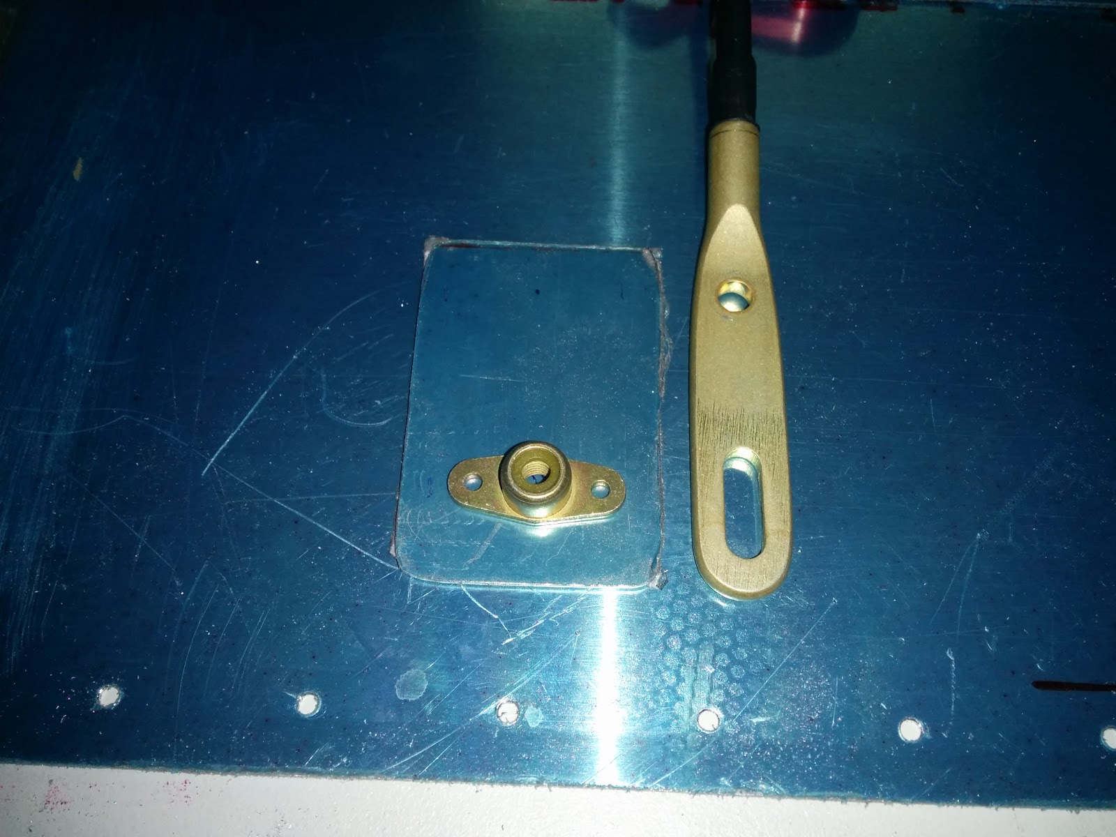
The ELT antenna for it will still be mounted vertically, on top of the cone, but I like the idea of a smaller portable antenna as shown above.

For the avionics that will be mounted in the tailcone (transponder, ADS-B, Stormscope), the proposal from this VAF post seems to be good:
Avionics attached to the corrugation
The avionics are mounted to the corrugation, which means that no changes need to be made to the main tailcone structure - good for both postponing the final avionics choices/mounting and for any future changes to it (worst case, changing the corrugation for a new one would be easy). This also means I don't need either the AHRS mount nor the ELT bracket from Vans.

Also like in the picture above, I plan to run at least a couple of conduits to the tailcone for all the cables. The only cables going further than the servos will be antenna cables and the ELT panel cable - I'll provide attachments points for those, and have one conduit running all the way to the back (for both the ELT cable and any future use of the vertical stabilizer conduit, or a possible whisker-type antenna if I ever change my mind about the wingtip antenna).

As part of the G3X, I'll also have pitch and yaw servos in the back, which Garmin provides a mounting bracket for (specific to the RV10 - per their manual):
Pitch Servo Installation
Yaw servo installation
While the pitch servo only uses screws for attachment, the yaw servo requires some riveting (the lower part of the forward bulkhead) - those will require special attention later.

To allow charging the battery and/or powering up avionics with external power, I plan to add an external power port with an APU Doubler  - those should go near the battery, probably to one of the sides.
Mouser's blog shows that the oxygen tank can also be installed inside the tailcone, but I decided against that for a few reasons: first, I want mine to be removable (no need to carry the weight around all the time); second, putting a bottle of pure oxygen right next to a potential source of sparks (the battery/contactor) sounded like a bad idea; last, I'd rather not do any refilling myself (results can be quite tragic, I'm told), so I'll leave that to pros and instead have a removable tank that I can attach inside the baggage compartment, much like this one posted to VAF:
Oxygen tank NOT near the battery
Also like in the above VAF post, I may consider the access door for the maintenance/modification flexibility:
Tailcone access door

The bulkhead corrugation is only part of the fuselage kit, though, so no need to worry about it yet (plus, the whole corrugation is apparently screwed into nutplates (manual page 33-10), so it's also removable - just not as easily.

Two other components I decided against mounting in the tailcone are the AHRS and the magnetometer - the AHRS can be up front, in a rigid place behind the panel or close to the wing (pitot tubing). Garmin recommends against installing the magnetometer in the tail, in favor of installing it in the wings (which makes sense to me). The only downside is that, if I use the recommended static port position on the tailcone, I'll have to run static air ducts all the way to the panel (but I guess that's OK - just one more thing to provide attachment points for).

Last, the battery itself goes in the back, but I haven't decided on the specific model yet (don't need to decide, for now) - I'm hoping that something like EarthX will be available and more reliable than it is today when that time comes, so I decided against a custom battery box that would lock me to a specific battery at this point. I'm planning to use Vertical Power's Primary Power System if that's out in time (they say it will be), but it still suggests using a contactor if the battery is in the back, so that won't need modifications.

So, in summary, the mods I'm planning which affect the tailcone are:

  • Antennas (see previous post)
  • 2 conduits into forward part of the tailcone
  • 1 conduit all the way to the back of the tailcone
  • running 2 static port ducts from each side to a T, and from the T forward to the panel
  • APU port on the side of the tailcone
  • GSA28 brackets (implies not setting a few rivets for now)
  • ELT mounting bracket below the VS

Disclaimer: None of the pictures on this post are mine, but there are links to all their respective sources. If you own any of the images and would like me to remove it, just leave a comment and I'll do it.

Research: antennas

This is a long delayed post, but only now I got to write it.

Since antennas are not part of the standard kit, I've been researching what antennas I need for the plane and how to position them.

My plan of record is to have the following avionics:
That gives me a pretty good IFR setup and a decent ADS-B setup (1090+UAT In plus 1090 Out).
That means I need the following antennas (confirmed from a Garmin representative about which devices can share antennas):
  • 2 GPS/WAAS/antennas (must be on top, one of them with XM)
  • 2 COM antennas (one on top, one on bottom)
  • 1 NAV antenna (shared between GTN and GNC, on wingtip)
  • 2 transponder antennas (GTX+GDL, on bottom)
  • 1 marker antenna (coax cable)
  • 1 ELT antenna (on top)
  • 1 stormscope antenna (NY-163, included in the WX500)
  • Maybe: 2 TAS antennas (top and bottom)
The tricky part is - all the antennas interfere with one another if they're too close together, so I have to figure out what ground plane clearance I need around each one.  I'm taking the following antennas as reference, and assuming that any other antenna of the same type will be similar - the frequencies are the lowest needed, which thus require the largest ground plane.

Top antennas:
  • Garmin GA57X (G3X GPS+XM) - 1565MHz - 4" ground plane radius
  • Garmin GA35 (GTN GPS) - 1565MHz - 4" ground plane radius
  • Delta Pop Top Mount COM antenna - 118MHz - 23" ground plane radius
  • ELT - 121.5MHz - 10" ground plane radius
Bottom antennas:
Top/bottom antennas:
  • NY-163 Stormscope antenna - 12" ground plane radius, away from skin current, 48" away from Transponder antenna, 12" away from COM antenna, within 6" of ventral fin, etc. etc. etc. (understandably, this one is picky, but can go on top or bottom equally)
  • TAS antennas (top AND bottom) - 6-9" ground plane radius, most forward position, bottom and top aligned
The problems here are:
  • COM antennas require a large ground plane
  • Stormscope antennas appear to be very picky
  • TAS antenna also appears to be very picky (great advice about the GTS800 antenna on VAF)
  • Top TAS antenna needs to be mounted forward where there's no metal, so it'll require me to fabricate a ground plane
Another nice gadget to have is a UWB antenna, which can boost 4G signal to the ground and get good LTE reception. I'm undecided on whether to actually install it, but it's easier to allocate space for it anyway.

In addition to all that, and to that the most complication, I'd like to have room on the bottom of the fuselage for a MotoPOD, which takes away significant belly area that could be used by antennas (I can probably live with not having the TAS, the UWB and maybe one COM when that's installed, but that would be suboptimal).

This was my first attempt at placing all the antennas (I only had overall dimensions for the MotoPOD, not the detailed shape, so I used a box):


(CAD file available here for anyone interested)

I posted this to VAF, and got lots of good pieces of feedback (also, it appears that mounting the ELT antenna inside the empennage fairing vs vertically is one of those endless discussions, like the primer wars). Highlights were:

  • My GPS antennas were too close - fixed.
  • If I want to put transponder and ADS-B antennas in the back, then the respective transmitters should also be back there (doable given they're remote-mounts)
  • Having one COM on top is a good idea
  • Do I really want the MotoPOD? I'd rather leave this one unanswered for now - if I plan for antennas away from the belly, I can decide later when I get to the fuselage.

So I'm sticking to this plan for now, and will plan the tailcone accordingly (a post on that to come later).

Links

These are various sources of information I used for this:

Overall antenna selection and placement:
http://www.myrv10.com/N104CD/panel/antennas/
http://nerv10.com/wcurtis/90Electrical/antenna.html
http://www.steinair.net/file/Suggested%20Antenna%20Placement%20RV-7_9.pdf
http://www.eaavideo.org/video.aspx?v=1136841468001

Bob Archer NAV antennas:
http://www.aircraftspruce.com/catalog/avpages/archer_antenna-1.php?PANEL=203
http://home.hiwaay.net/~sbuc/journal/sportcraft.htm
http://www.chiefaircraft.com/aircraft/antennas/bob-archer.html

Whisker-type NAV antennas:

ELT placement:
http://ivankristensen.phanfare.com/2292606_5182951
http://weaselrv10.blogspot.com/2011/04/elt-antenna.html

Marker beacon:
http://www.vansairforce.com/community/showthread.php?t=72497&highlight=ground+plane+antenna

Cabling:
http://www.vansairforce.com/community/showpost.php?p=420934&postcount=11
http://www.hol4g.com/webpdf/AND_474.PDF
http://www.vansairforce.com/community/showthread.php?t=75839&highlight=RG58

MotoPOD:
http://www.vansairforce.com/community/showthread.php?t=125824
http://www.vansairforce.com/community/showthread.php?t=128698
http://www.matronics.com/forums/viewtopic.php?p=270599&highlight=&sid=c63283c50cde4d9eaffcf6fb9dd42bda

Horizontal stabilizer complete!

The horizontal stabilizer is 100% done after only 137.1 hours of work (and re-work, and re-re-work):
Completed Horizontal Stabilizer!
The longest part of it was riveting the ribs to the skins - several rivets had to be set multiple times (they're close to tolerance, and I assume the layers of primer bring me even closer to that, so I had to up-size a few of them):
Riveting ribs to skins

Riveting ribs to skins
Another important step was to figure out where to install nutplates for bonding with the elevators (where the static wicks will live). From several posts from other builders, such as Mouser (thanks again!), I ended up deciding on using the hinge brackets themselves, and I wanted to use the most inboard brackets as that reduces the forces acting on them:
Bonding strap screw hole

Nutplate for the bonding strap screw

Once that was done and every inside rivet was checked and re-checked (and some replaced), I attached the rear spar to the ribs and then to the skin:
Rear spar ready to be riveted to the HS
While attaching the last side of skin to the rear spar, I had a small misalignment issue:
Oops, those holes don't match!

It was less than 1/32", but enough to make rivets not go in straight:
Diagonal rivets :/

I eventually fixed it (with help from VAF once again!) by slowly using a dimple die to bring the skin to alignment around a hole, then clecoing the next hole (and repeating that for every other hole in the spar).

Now, on to finish the elevators! (already about halfway done)

Time lapse:


Total horizontal stabilizer time: 137.1h
Total horizontal stabilizer rivets: 1292
Total empennage time: 311.5h
Total empennage rivets: 2101