I terminated the EFII battery cables and connected the batteries to those plus the main bus, secured the whole thing with wax lacing, and attached the hall effect sensors with the mounts I had 3D printed:
Batteries installed and connected
Probably unnecessary (they were already a tight fit), but I also ran some wax lacing to secure the sensor mounts more firmly:
Hall effect sensor brackets secured around battery cables
Another tense moment turning it on, but everything worked! Well, everything except the hall effect sensors, which were giving no reading in spite of being connected to the G3X's GP6/GP7 inputs. A lot of troubleshooting later, and I realized that even in Stein's original wiring diagram, they missed the fact that the "LO" side of that connection also needs to be connected to a ground pin (per Garmin's manual: "When using the GP6 and GP7 inputs for general-purpose voltage sensing, including position sensors and user-defined analog parameters, the corresponding GP6 LO or GP7 LO pin must be connected to ground."):
SteinAir's original wiring diagram, without a connection between GP6/GP7 LO and GND
Instead of adding splices to both LOs, I simply moved the sensors to GP3/GP4 which already have the LOs internally connected to GND (and are actually the pins that show up in Garmin's manual for this connection):
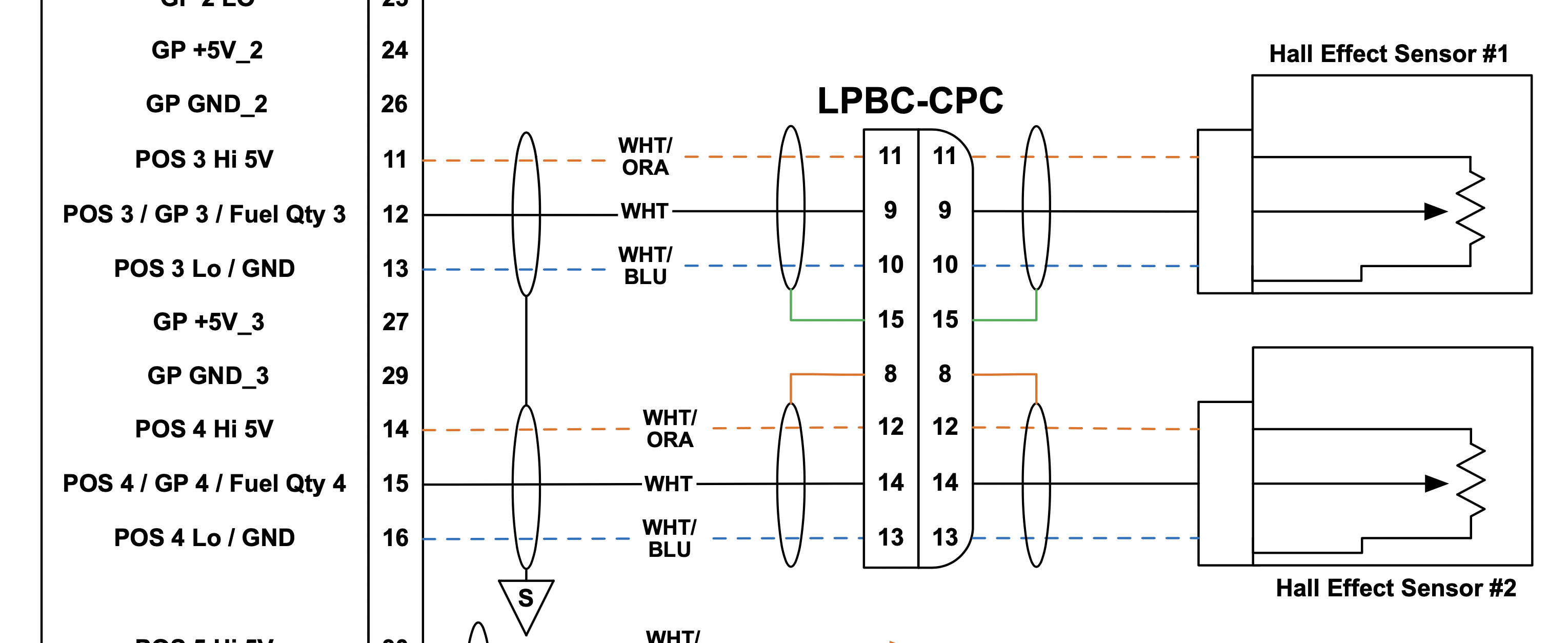
My updated wiring diagram, moving the hall effect sensors to GP3/GP4
Moving to the other inputs required a bit of surgery to split those +5V pins again (but to the naysayers that say that a box full of random pieces of wire is useless, I used a white/orange piece with the socket for this):
Hall effect connectors on the GEA24 side after modification to use GP3/4 instead
Once plugged in, I immediately got a reading - however, the reading was something like -13A, which seemed wrong. I then realized Garmin's documentation doesn't match Amploc's for that sensor - Garmin says the sensor should read 2.5V at 0A, however the KEY100 documentaiton says it should read 5V/2.2=2.27V. At 15.9mV/A, that 230mV difference makes it read a significantly wrong value - I calculated the offset would be about -14A, but then I also realized that these must have significant variability, because 8.8/8.9A was the actual offset I had to apply:
Offset that had to be configured for KEY100 sensors
Proper current readings after adjusting the calibration
I had previously made a small hole on the tunnel cover to run wires into the tunnel from the panel, thinking that I could just de-pin connectors and pull the wires out when I needed to remove that cover - but it became apparent that assembling and taking apart the GHA15 connector is more painful that I expected, so I enlarged that hole enough to let the whole connector go through:
Larger hole on the tunnel cover for the GHA15 connector to go through
Tunnel cover with wires going through it (no edge protection just yet)
I also took the opportunity to trim and terminate the center console wiring (I honestly wish I had just shipped the whole plane to Stein to get those lengths right from the start), and changed the gender of the pax connector so they can't be accidentally swapped - I'll later add some Clickbonds cable ties to secure it alongside the engine cables and underneath the throttle quadrant:
Audio wires running underneath the throttle quadrant
Wires running through the center console for pilot and passenger audio
Pilot audio connections inside the center console
I had planned to run the flap wires over the top of the tunnel, but then changed my mind as it was easier to secure the whole thing by running it through the side (plus I had already added Clickbond fasteners near the flap torque tube for them):
Flap motor wires running near the flap torque tube
For the pitch trim motor, I had (way back when I built the tailcone) added a beefy 28-pin connector, thinking of the ELT connection plus anything else that would go in that area. I now realize that was way overkill, plus the connector was too far from the trim motor, so I drilled out the rivets that attached it, and replaced it with a simple Molex SL connector:
Pitch trim motor with previous CPC connector (overkill)
Pitch trim motor with Molex SL connector
More wiring to come - the next big thing is finishing up and securing the main panel bundles for good, and terminating the wing root and stick grip CPC connectors.