Once the oil cooler box was riveted, we installed the brake hoses, starting with the ones near the corner (harder to get to):
First brake hoses attached to parking brake and ALIR
then the ones that connect the pedals:
All brake hoses installed in place
Top view of the brake hoses, showing that they don't touch
Finding the right clocking and direction for all of those to avoid contact took some trial and error - partly because I installed the ALIR a bit further forward than Aircraft Specialty suggested (to have easy access to all the ALIR ports), but also I didn't really want to have all the hoses coming out the center of the pedals 'cause they'd be hitting one another when they moved.
With this, the only steps left on this section are attaching the brake fluid reservoir and filling up the system with brake fluid.
Before final attachment of the engine mount or brake hoses, but after insulating the bottom of the firewall, we riveted the oil cooler box and insulated it:
Oil cooler box riveted to the firewall through the titanium foil
This was a small step to resolve a dependency chain where we wanted those rivets done before installing hte brake hoses, which in turn was much easier to get done before riveting the panel, which in turn had to be done before insulating the top of the firewall.
Once all insulation is done, we'll actually reattach the engine mount and hang the engine for good.
We riveted the firewall doublers to the firewall for attaching the sensors:
Firewall doublers riveted in place
Firewall, showing flush doubler rivets
With that, the bottom part of the firewall is ready to insulate (which will be the topic of a separate post, on section 46).
Meanwhile, I also match-drilled the new laser-cut/anodized O2 distributor flat back covers I had made (which, unlike the standard ones, will give me cabin cover clearance, without needing custom-length spacers), and attached them to the aft overhead panel - that made the distributors stick out the bottom just the right amount that the rubber band sealed them up for a nice finish:
New O2 distributor backing plates clamped to the original for match-drilling
Aft overhead console insert with lights and O2 distributors
Top side of the aft overhead console insert with new O2 distributor backing plates
I then match-drilled the tailcone antenna holes (COM, Stormscope) from the doublers/drilling jigs, and attached the tailcone antennas:
Top COM antenna (left), Stormscope antenna (center) and ELT antenna (right), installed in place
Connection to Stormscope antenna
Bottom COM antenna installed in place
Transponder antenna installed in place
In the tailcone, I also attached the autopilot servos:
Pitch and yaw servos attached in the tailcone
and the avionics shelf and the LRUs that go there, including terminating the GTS800 cables (with those annoying QMA connectors):
Avionics shelf attached in the tailcone
GTR20 (left), WX-500 stormscope (center) and GTS800 TAS (right) installed in tailcone, with TAS bottom cables terminated and attached
(for reference, if anyone chooses a similar antenna/GTS position than I did, the total cable lengths was around 7.6ft)
For routing the Stormscope cables, the autpilot servo cables, and the transponder antenna cable, we attached some Clickbond fasteners just below the shelf (conveniently using the lightening hole on the shelf for one of them, and avoiding the GTS attachment nutplates):
Tailcone avionics shelf with Clickbond fasteners underneath it
We then started working on the GPS/XM antennas, that go inside the overhead console (extra annoying to position doublers):
GPS antennas sitting in place on the cabin cover
All top antennas - GPS (x3), COM, Stormscope and ELT
I started preparing the wire bundles to run from the tailcone forward, starting by de-pinning the forward side of all of them, and reducing the sleeving to be just about the length that takes them into the conduit, then splitting the WX-500 wires from the GTR20 wires (for some reason SteinAir put them in the same bundle, at a random distance which doesn't match my layout):
Single bundle with GTR20 and WX-500 cables made by SteinAir
GTR20 and WX-500 wire bundles after splitting them
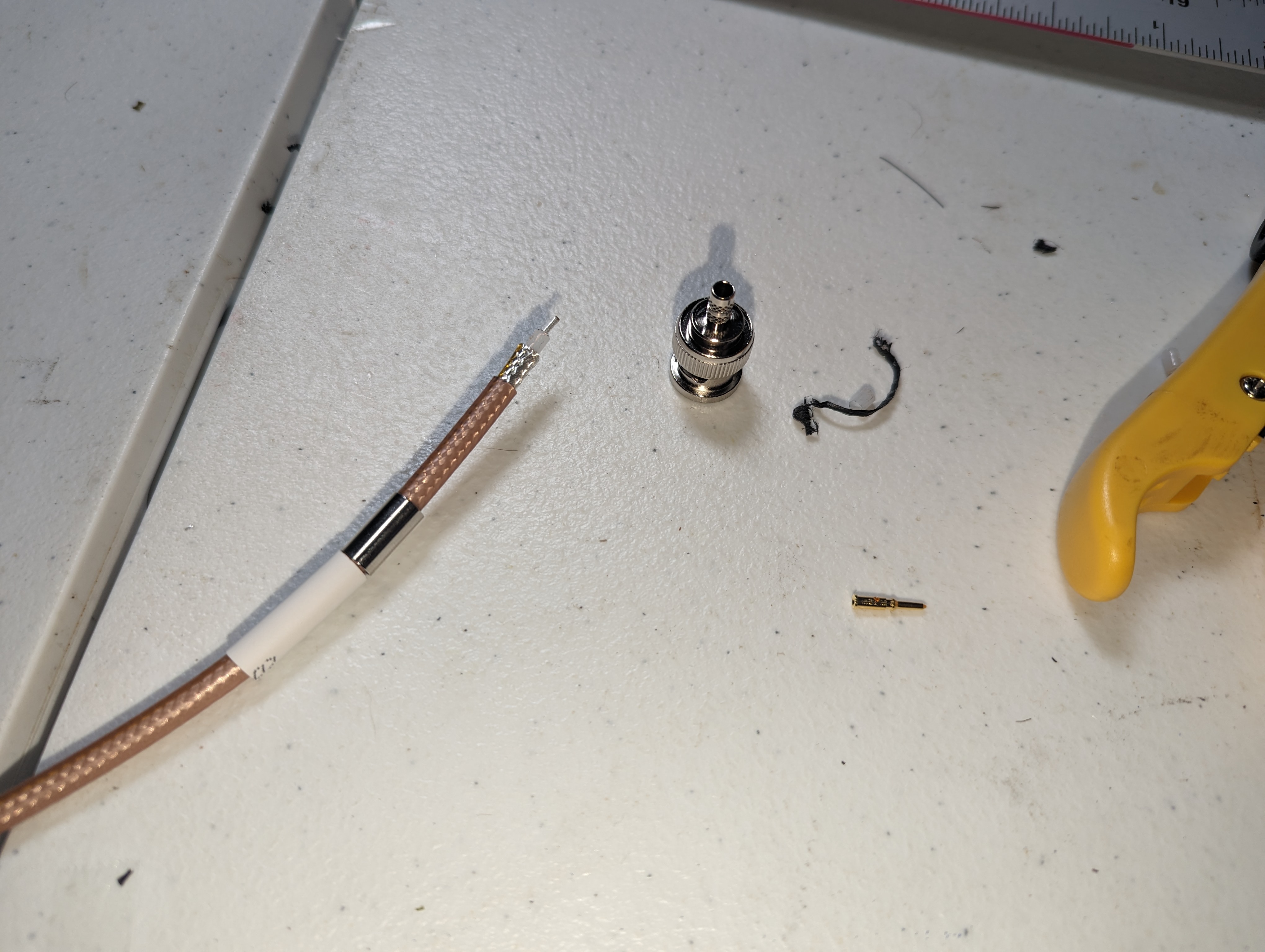
Still in the tailcone, I made the GTR20 antenna cable (from a leftover 4ft piece of coax):
Trimmed-back coax cable and connector ready for crimping
GTR20 connected to its antenna
Once the panel was riveted in place, we also started installing components there, like the AFR and alternator regulators:
Spartan3 AFR sensor controller installed in place
Alternator regulators installed in place
Still lots left to do in avionics - next is actually running all wires between the tailcone and panel.
I get a lot of questions about stuff I design to be either 3D printed or laser cut / CNC bent.
I design everything in Fusion 360, and you can find all the designs here (Fusion 360 format, but you can export to other formats using their free version).
Some of the designs already there are:
Antenna doublers for the GA-35, GA-57X, GA-58, GHA15, Delta Pop COM antenna, and NY-163 (drilling jig only) - inserts were added directly in the SendCutSend order interface:
Laser-cut antenna doublers, some with nut and stud inserts
Baggage door latch bar - a bar for the baggage door lock/cam that has the tip at an angle, to pull the door in
Control column measuring jig - for adjusting the elevator pushrod lengths (page 39-10 step 1)
Door bracket locating bar - static bar to use in place of the gas strut for drilling (page 45-16 step 2)
3D printed door bracket locating bar
Door lock indicator - a flat plate to insert into the door third-latch bar to indicate that it's closed
Door closed indicator attached to latching bar
Door closed indicator inside door
Dual VA-260A shelf - a version of the OP-48 tailcone shelf made for two ribs (twice the width), with my positioning of relays
Tailcone shelf with relays
Elevator bellcrank jig - used to position the tailcone bellcrank in the neutral position (page 11-7 step 2)
F-10112-R GTR20 mount - a variation of OP-41 that fits and has mounting holes for the GTR20
GTR20 tailcone side mount
Fan doubler - for panel cooling/defrost fans
Panel fan openings with doublers riveted in place
Firewall TTP-S drilling jig - drilling jig to get all the holes for TTP-S spherical grommets drilled. It has a nice feature of being composable (you can use multiple of these attached to each other through the jigsaw-type tips/holes to make multiple holes):
Firewall spherical grommet drilling jigs in place (3 of them)
Hall effect sensor mount - a way to secure the KEY100 hall effect current sensor to a pair of wires (#2/#10) and hold its connector in place (wires get hot - use a high-temp material if printing these! I did MJF with PA-12 nylon):
KEY100 hall effect sensor mounted to battery cable
O2 distributor backing plate - the Mountain High distributors' backing plate has a flange (which you can flip up or down), I wanted one that's flat since that gives me the perfect height without having to carefully trim 16 spacer bars to the same random length. Includes nutplate holes, and must be anodized to match the originals.
O2 distributors with custom backing plate
O2 mount box - featured extensively in prior posts, this is how I protected the O2 bottle in the baggage compartment.
O2 box in baggage area
Spartan3 AFR case - I'm using the Spartan3 AFR sensor board with the EFII System32, but I changed the connector to one that will latch better, and wanted something with actual holes to secure it through, so I remade their case to fit those:
Spartan3 AFR controller in custom case
As for actually making these, I use Oshcut for anything that needs bending (becaue they actually make dimensions match my design), SendCutSend for just laser cutting (usually cheaper than oshcut, and they have the option of adding inserts), and Xometry for MJF printing. (and for clarity, I'm not sponsored or get anything from any of them for the callout).
Hope some of these are useful for someone else too.
Now that all firewall attachments (holes, doublers, nutplates, etc.) are done, we finally started the firewall insulation, using the fiberfrax+titanium foil method that's documented in many places (here, here, here/here/here). We started by taking a mold of the firewall and cutting 3 strips of titanium to be attached vertically, the center one having folds and cuts to fit into the recess:
Taking a paper mold of the firewall for cutting titanium
Measuring the cuts on the center part of the firewall titanium
3 parts of titanium foil covering the firewall (not final-trimmed yet)
We left about 1.5" of overlap between the center titanium foil and each of the other two - could've been just 1", but I wanted some room to have rivets holding it down without hitting the flanges that are against the recess on the inside.
The Fiberfrax, in addition to its impressive thermal conductivity (or lack thereof), turned out to be a very easy, mat-like material:
Roll of Fiberfrax
To attach it, we cleaned the firewall with acetone, marked areas where we didn't want the fiber (basically places where some part contacts the firewall), then spread drizzles of Firebarrier 2000 on the rest, and especially near the edges of where the fiber would be - then we cut out the unwanted parts with an exacto knife (again, the Fiberfrax is very easy to cut, it doesn't tear if you're careful):
Applying Firebarrier 2000 to the firewall, to attach the fiberfrax
Fiberfrax attached to bottom part of the firewall, minus cutouts for firewall components
At this stage, we also had a circular dependency - that we wanted to rivet the oil cooler mount (section FF1) and attach brake hoses (section 38) near the firewall before attaching the panel (section 41), but also had to insulate the firewall before riveting the oil cooler mount - by simply doing the bottom-left part of the firewall first, then riveting/attaching hoses and the panel, then insulating the top part of the firewall:
Bottom-left section of the firewall insulation attached in place
I'll be posting separately about those sections, and the next step on this section will be attaching the rest of the titanium foil and top part of the fiberfrax.


