Research: empennage mods

Another two pieces of research on mods the empennage I've been looking at are fitting a camera to the top of the vertical stabilizer and adding rudder trim.

Having flown Cessna 182s with proper rudder trim, I'm spoiled enough that I want one as well :)
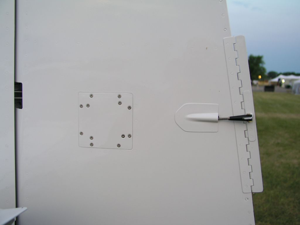
I've found several other builders who added rudder trim (link 1, link 2, link 3, link 4). It appears that most of them use the same recipe, originally conceived by Don Orrick, which involves adding a servo inside the rudder to control a rudder trim tab (video of it working):

Image from www.myrv10.com
Another alternative is the method proposed here, which doesn't add a tab, but rather cuts the trim out of the rudder material itself. Yet another alternative is that offered by Aerosport, which isn't electric but requires no modifications to the rudder itself - it acts directly on the controls. Skunk Works also has a kit which IS electric (they have manual and electric options) and requires no external modifications, so I'll probably get in touch with them to request more info before deciding.

As for the camera, my ideal setup would be some kind of "box" at the top of the vertical stabilizer where I could fit any camera I want (thus allowing for an easy upgrade to newer/better cameras as those become available), yet with the lens sticking out enough that the image doesn't cut off at the bottom by the stabilizer cap. I've seen several builders who modded the cap by adding a hole and molding around a specific camera (link 1, link 2):

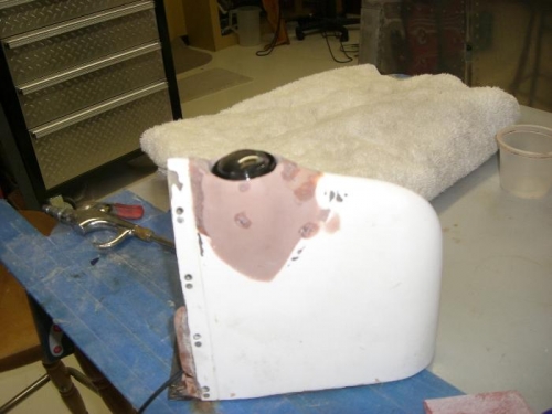
Image from Gaylon's kit log
I don't like that, as I really want to add be able to use the GoPro 15, Contour 7 or Virb 9 as they come out in the future, so I'm still looking for another solution (and as a last resource I can design my own).

Another issue is how to run the wires to the camera (at least for power, though if I do use the G3X as I intend to, it supports video input as well). Apparently the easy way is good enough, which is to drill holes through the ribs and run conduits through them, with or without reinforcement plates around those (link 1, link 2). An alternative is to use the lightening holes and fasteners.


Vertical stabilizer skin

Yesterday and today I did the fitting of the spars into the skin, then clecoing them together:


The first thing to fix was that the inner ribs were not straight, but rather bowed:


I remembered there being an item in Section 5 of the manual talking about fluting, so I went back to read it, and also watched a few videos (video 1, video 2) describing a good technique to do it, as well as some builder logs saying they did flute the vertical stabilizer ribs. With the fluting, it looks much better:


I'm also glad I'm leaving the blue vinyl on so far, as the one flange I fluted without it (because it was coming off) had small creases from the plier:

Fluted with vinyl on (no creases)
Fluted without vinyl on
Again having in mind the issue of denting the skin with the front ribs, I fitted them into the skin, clecoed the bottom, and tried to bend the skin over them to cleco the top - it then became apparent that I hadn't removed enough material, so back I went to remove about 1/16" more (1/8" or so total - bringing it very close to the minimum hole-edge distance) then they finally fit without leaving any dent:

You can see the lifted vinyl to the right of the rib from what would have been the dent, from my first fitting attempt
I put back the rib assembly together and fit the whole thing into the skin, then clecoed it (wife helped with that part - her first contribution to the project :) ):


Time lapse of the whole thing:


Total vertical stabilizer time: 18.0h
Total workshop time: ~23.0h

Vertical stabilizer coming together

Next instruction was to deburr the edges of all remaining parts in the VS, so I did that, then clecoed the parts together and drilled the common holes (had to use the long 12" #30 drill for the front sections). This is now starting to look like a proper vertical stabilizer:


Lots of little bits to deburr:

Before
After
From my research (and mostly luck of finding that one piece of text), I also found that many builders dent their skins by not trimming the front corners of the VS skeleton parts, so I trimmed about 1/16" off with the saw (curving around the edges), then used the file to smooth it out.

As usual, here's a time lapse (better camera position this time):


Total vertical stabilizer time: 13.8h
Total workshop time: ~22h

Holiday work: completed vertical stabilizer rear spar


Took the whole day to work on the project and managed to complete almost all the steps for the rear spar (except drilling the upper attach bolt holes, as I realized I don't have the required 3/16" drill bit).

This is starting to look like an airplane part
Ready to drill the final holes through all parts

They say clecos are one of the pillars of sheet metal work :)
First time using this microstop countersink, so took a while to adjust it (I used the trimmed part of VS-1004 and an AN426AD4-4 for that):


Shiny machine-countersunk holes

Time lapse:


Total vertical stabilizer time: 9.5h

Total workshop time: ~22h

Research: exterior lights


While trying to determine what else I might be missing for the empennage kit, I decided to do some research on lights - specifically, what lights I'd want on the empennage. This involved re-reading all the details of AIM 4-3-23, then looking at products. Some popular brands appear to be Aero LED, Whelen and Aveo. Looking at the products, they all seem pretty similar, but one specially stood out - the Aveo ZipTips:

(image copyright Aveo Engineering)
They also have a nice option to add lights to the trailing edge of the wingtip, effectively allowing me to only have lights on the wingtips if I want, which sounds great (less wires, less installation work).

That said, I do want to have beacon lights so I don't go flashing those superbright strobes at the ramp (like I have to in the DA40). They seem to have good (though nothing out-of-the-ordinary) beacons too, like the RedBaron XP, so I may as well go all in and get everything from them. As for the position of the beacon, I'm thinking of putting it down at the belly and keep my vertical stabilizer clean (and hope that it doesn't add any noise to the antennas).

I've written to the local Aveo representative asking for a demo, I'll post an update if I get it.

Vertical stabilizer: rear spar caps (now with the band saw)


With the band saw the trimming work became MUCH easier - even without being too powerful, it cuts through aluminum like it's butter. I did the second rear spar cap with it, giving a much better result than yesterday:


I then drilled the holes between the rear spar and the rear spar cap:


It was also time for my first mistake (thankfully it was a small one) - I misunderstood the drilling instructions and started drilling the rear spar cap against the rear spar's flanges, instead of the web. The flanges were meant to get #40 drills, rather than 1/8", so now I have 3 flange holes that will need larger rivets (after the third hole I realized the mistake and started doing it properly - you can see 3 clecos sticking out from the top of the flange).

Time lapse of the whole thing:


In the time lapse you can see I had a small issue with the compressor - it was rolling inside the (half-built) soundproof box, and ended up laying on the drain valve. I was afraid the valve could break, so I had to drain it (to make it lighter), lift it back into place, then put some blocks of wood to hold it in place.

Total vertical stabilizer time: 4.0h
Total workshop time: ~21h

First cut


After a lot of work setting up the workshop, inventorying parts, reading all the introductory sections of the Van's manual and getting ready, today I finally go to start some real work on the parts. I started by picking all parts needed for the vertical stabilizer (main skin not shown):


First instruction for the vertical stabilizer is to trim two parts (VS-1004) at an angle. As I had learned in the RV course, this could be done with the Wiss Snips (plus, the manual says having a band saw is optional anyway), so I carefully marked them and took the first cut, leaving some margin to make it actually straight later. I also took the opportunity to test making a time lapse of the building:


Turns out using the snips twisted the part a lot (this is thicker aluminum which doesn't come back to the original shape as easily):


It still unbends fine if I clamp it:


But at this point it was clear that no, this was not a job for the snips - I did need a band saw to do a proper job. So after half an hour of work in the vertical stabilizer, I stopped, went online to do some research on band saws, found out what kind of blade I needed (14 teeth per inch or more), saw that both Harbor Freight and Home Depot had inexpensive models, went to both to see them in person, ended up concluding that the Ryobi and Central Machinery ones were pretty much equivalent (they look almost identical except for colors and minor details), confirmed that reading online reviews (on the phone at Home Depot), and ended up getting the Ryobi:


Setting it up took some work, specially to get the blade properly aligned (too many adjustments), so by the time I was done it was 9pm, probably too late to make noise cutting aluminum, so I called it a day and plan to test the saw and cut those tomorrow.

Total vertical stabilizer time: 0.5h
Total workshop setup time: ~20h

Empennage kit is here!!


After a grumpy FedEx delivery guy who kept complaining about the size and weight of the box, it's finally here!

The box
Cracking it open
First sight of the contents


Reading material 
Just a few rivets...should be done in no time (not) 
Contents after unpacking the first layer (*some assembly required)

Now on to inventorying the whole thing...

More workshop setup

Over the weekend, Chris (mentioned in the first post) also let me have his compressor while he's not using it, saving me several hundred bucks, at least for a few months - it can be seen in the pictures below.
We also decided it was time to organize our tools, so we got a proper tool chest.
Few things are missing in the workshop to get started - a bench vise, bench grinder, and a soundproofing box for the compressor (it's loud!).

Before
After - a tad easier to work :)
The culprit


Tools

Finally got all my tools today and inventoried them.

Unpacking

Organizing (kind of)
Dimple dies and rivet sets
A bucketload of clecos

Workbenches done

Following the EAA Standard Workbench plans (published on Sport Aviation January 2010 edition), we built two workbenches we can use for working on the RV10.

Building the top frame
Attaching the legs 

Attaching the doublers
Bottom frame
(we ignored the original instruction of building it separately - this seems to give a better fit) 
Attaching the top
(that car will soon have to stay outside)
Adding the last screw

In the last week I also finished reviewing the list of tools that we'll initially buy, and comparing prices between different stores (Aircraft Spruce, even with the EAA member discount, is still more expensive than others, so they won't get my order). I'll make a separate post when they arrive.

It begins! (Dimpler arrived)

Today I received the very first shipment related to building the plane - no, not the first kit yet, since I really need a shop set up first - but my first tool, a DRDT-2 dimpler:

60lb box from Aircraft Spruce
The parts that come in the box
The assembled dimpler

Even better for me, I didn't have to pay for it - a friend gave it to me as a gift for hosting him while he was visiting the area :)