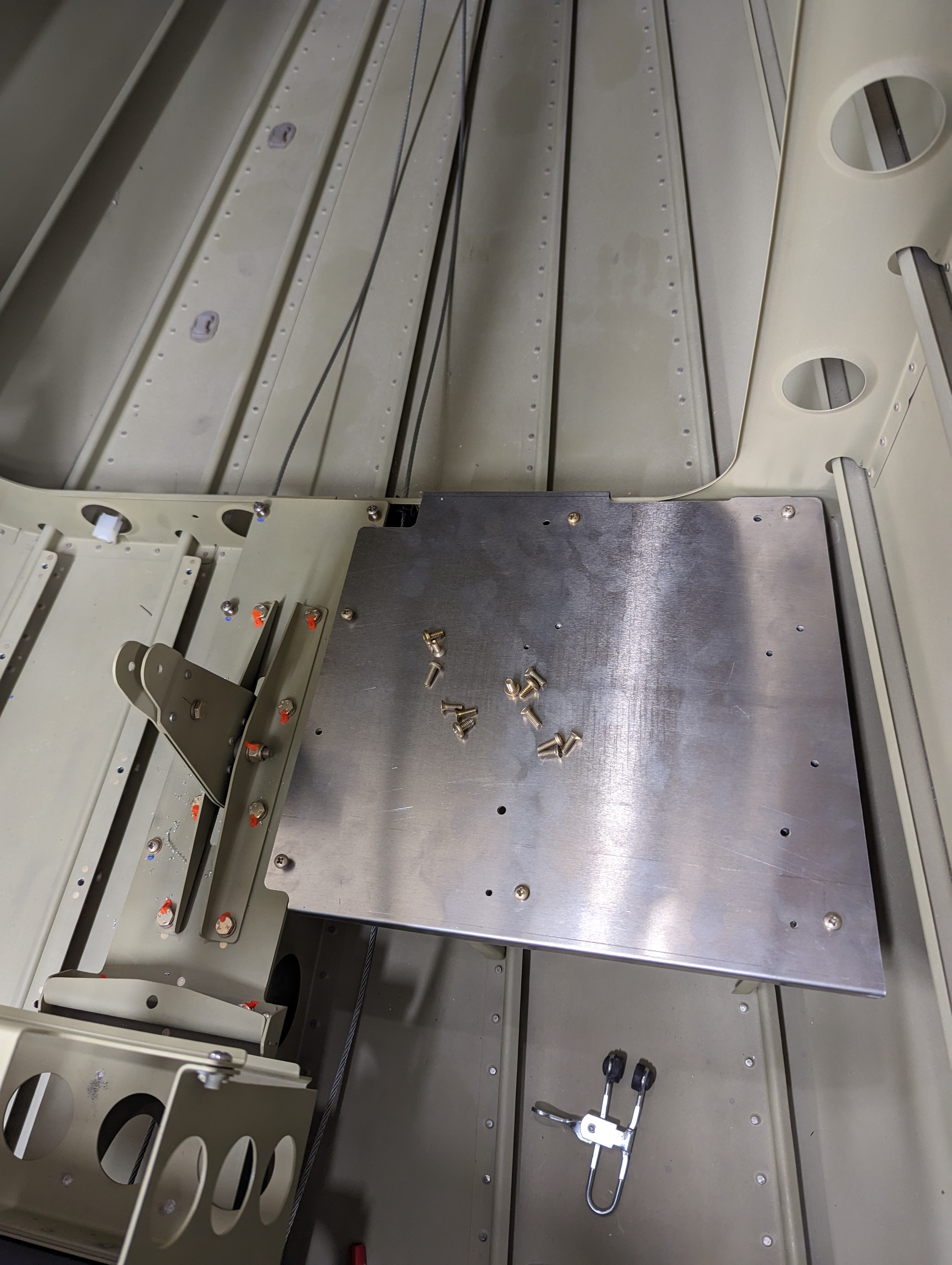
As an additional item in section 9, I confirmed that it'd be very hard to screw in the trim cable brackets onto the trim cables with any precision, so I separated the brackets and modified the holes so they're attached with screws instead:
Pitch trim cable brackets attached with screws instead of rivets
I finished the last remaining items on the tailcone section by connecting the main power wires, starting with the external power port and relays:
Overvoltage crowbar and diode for external power port
Contactors, overvoltage crowbar, and external power port connected
The crowbar requires a circuit breaker (which is actually disengages external power when there's overvoltage), so I placed it on the upper portion of the baggage bulkhead to make sure no baggage would hit it (with a larger hole on the corrugation so it's removable without touching the breaker):
Overvoltage module circuit breaker going through the bulkhead and corrugation
Overvoltage module circuit breaker wired to relay and ground
I had originally planned to have a separate ground cable for each battery, but it quickly became apparent that this would cause trouble at the ground point, so instead I fabricated another copper bar to connect the two batteries:
Grounding point with too many cables coming from the same direction
Batteries with grounds connected by copper bar
I also installed the foam spacers that came with the EarthX batteries, by splitting them in half and attaching them to each side of the battery case (that leaves the side holes open for some ventilation):
Battery cases with spacer foam installed
I'll leave the actual battery installation and securing wires to be part of the avionics section since it also involves connecting the EFII battery wires, Hall Effect sensors, etc. and call this section fully complete.
I added a lightening hole to the avionics shelf (keeping its edge about 3/4" from the nearest screw holes):
Tailcone avionics shelf with a lightening hole removed with the fly cutter
and then riveted the left shelf nutplates in place (for the contactors):
Left-side shelf with nutplates riveted on
I drilled holes for an AN366F nutplate on the bellcrank mount to use as the main grounding point, only to realize that the edge of the nutplate would collide with the bellcrank rib:
Battery mount bracket with nutplate hole for grounding point, one rivet hole going beyond the edge of the underlying part
Many facepalms later (if only I had shifted the position just a bit...), the solution I picked was to switch to a MS21081-4 corner nutplate, which can still use two of those holes (that nutplate also seems relatively hard to find, so I ordered mine from a shop in Alaska!):
Battery mount bracket with a 90-degree nutplate to stay clear of the underlying part
With that in place, I removed primer from the surface that will have contact with the washer, for better conductivity:
Battery mount grounding point with primer removed
I then re-assembled the whole thing, re-connected the pushrod, attached the servo mounts, etc.:
Tailcone area with battery mount, left shelf, and servo brackets back in place
The only real steps left for this section are to final-install the contactors and batteries.
I attached the two battery boxes together and to the bellcrank mount:
Battery boxes attached to each other
Battery boxes attached to each other with double-flush rivets, and to the bellcrank mount with flush rivets
Battery boxes attached in place with battery mockup
Battery boxes attached in place with battery mockup
For the contactors, I wanted to extend the OP-48 AHRS support bracket to span both ribs:
Original OP-48 shelf plus a paper extension for taking measurements
It took a bit of measurement and fine-tuning to get the holes in the right positions:
Sketch of the modeled shelf's web with measured hole positions
Rendering of the modeled shelf
Before sending this for fabrication, I 3D printed a thin version of it to confirm the layout:
3D printed shelf model
3D printed shelf model screwed in place
With just a few minor adjustments, I had the part laser-cut and CNC-bent in aluminum, and it fit pretty well:
Aluminum shelf screwed in place
Only exception was that the aft flange was too far aft (I tried to adjust both flanges slightly to not make the fit so tight as it was before, but clearly I adjusted too much, so I had to make a shim:
Shim for making aft flange of the shelf flush with the bulkhead
For connecting the 3 contactors (one for each battery and one for external power), I used a copper bar, which also held them in relative position for match-drilling the attachment holes into the shelf:
Copper bar with 5/16" holes for contactors
Contactors connected by copper bar, holding relative position
Contactors with attachment holes match-drilled in place
Last but not least, I cut a smaller right-side shelf for the GTS800 and WX500 (which I'll post about on my next avionics update).
Next on section 10 is just priming these parts, installing nutplates, and final-installing the relays and batteries in place.
To finish up section 12, we riveted the empennage fairing attachment nutplates:
Empennage fairing attachment nutplates
I had a gap on the leading edge of the vertical stabilizer fairing of about 0.05" - I sanded it to remove the gel coat then added a few layers of fiber there to extend the edge:
Gap between vertical stabilizer skin and fairing leading edges
Fiber laid up onto vertical stabilizer fairing leading edge
Vertical stabilizer fairing leading edge after sanding
After a bunch of sanding and filling and primer, this part was done. I also took the opportunity to finish sanding and prime the empennage fairing, which means section 12 is now complete (except maybe for final attachment of the screwed-in parts which will happen much later).
Before joining the tailcone to the fuselage, I cut and drilled a tray for avionics (to be refined later when I actually have the avionics to mount):
Match-drilling the tailcone rails to the avionics rack
Avionics rack screwed in place
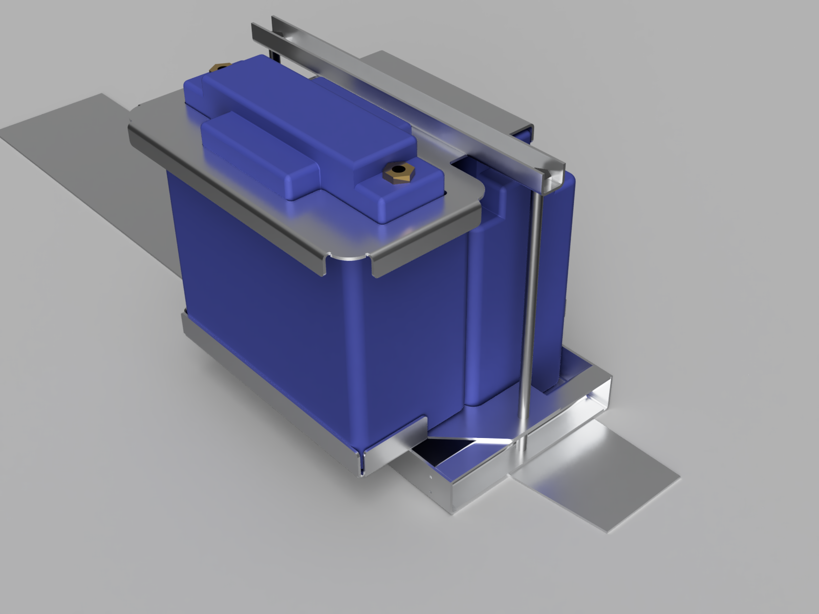
With my intention of using 2 EarthX batteries, I had to figure out how to attach them (the standard bracket doesn't do a good job since the batteries are smaller).
Physical parts for the battery installation
I took that as an excuse to learn Fusion 360, model the parts, and sketch some ideas there:
I started with some custom brackets to attach it to the existing structure, unmodified:
Higher "shelf" for the second battery
Battery hold-down bracket that only attaches the EarthX vertically
Battery hold-down bracket that fits the EarthX shape all around it
Those would work, but they add some weight and are not really "elegant" solutions, so I tried a few options with EarthX's official box (which I also had to model):
Attaching the batteries with the EarthX official box
Attaching the batteries with the EarthX official box, laterally
(if these models are useful to anyone, you can find them here)
I showed this to Van's support and they didn't like the idea of the underlying ribs being loaded asymmetrically, so I ended up cutting both sides and using their battery boxes:
EarthX battery boxes
The goal is to double-flush rivet them (with a spacer inbetween), so I had to do some testing on thicknesses and rivet lengths before cutting the spacers (ended up with 0.063" for the spacers):
Double-flush rivet thickness testing
Battery boxes clecoed together with spacers
Machine-countersunk battery box holes
I cut of the sides of the original battery mount and attached the new joined boxes to it:
Modified battery mount
Battery boxes on the new battery mount
After primer, I'll rivet this all together and effectively complete section 10.
After detaching the rudder and vertical stabilizer (hopefully for the last time before final assembly), I started to comply with SB 18-03-30. As previously mentioned, the elevators were at the high end of the required travel range (at 30˚ up, with the required range between 25˚-30˚), but at that position they weren't being stopped by the flanges of the horns, making compliance required:
Filed-down elevator stop angle in an attempt to comply with the SB
I measured, and if only the elevator stop angles hadn't been filed down to give the full range, then the horns would still touch them at the flange, and the movement would only be down to 28˚ up, still within the allowed range, so I removed the elevator stop angle and replaced it with a new but equal (just unfiled) part:
Removing the elevator stop angle
New unfiled elevator stop angle clecoed in place
New elevator stop angle riveted in place
I also opened up a bit of the rudder's leading edge to give room for the grounding strap without interfering with the attachment:
Grounding strap hidden behind the leading edge
Leading edge after removing additional material
New leading edge gap exposing the ground strap attachment point
Grounding strap attached to the rudder
Finally, I 3D printed the template to adjust the elevator pushrods:
3D printed elevator pushrod template with holes for clamping
Elevator pushrod template clamped in place
With this, the last steps on section 11 are now left for the final assembly at the airport.