Showing posts with label research. Show all posts

Experimenting with paint for the interior

Even if I go with one of the many interior cover options, there are several parts that are still exposed in the fuselage's interior, which will need to be painted. I wanted a matte gray tone, and wanted something that I'm likely to be able to buy more of later (e.g. for touch-ups or future mods), so I picked up a few spray cans at Home Depot to test them out (and it's surprisingly hard to find spray paint without primer). I applied them on the bottom part of the baggage floor so it's not visible later:

Various paint types tested on the bottom of the baggage floor. Left to right: Rust-oleum chalked country gray, Rust-oleum chalked aged gray, Rust-oleum pro dark machine gray, Behr Chalk classic noir

I liked the 3rd color (dark machine gray) best, but it's unfortunately quite glossy (notice the reflection of the can on the paint), so I'll likely go with the first one (country gray) instead. The other two were matte but too dark or too light.

More on antenna positions

For antenna positioning, I tried to put the forward tunnel parts around the place they'd go, and reailze it gets really crammed in there (plus, forward of the fuel valve goes the EFII pumps, filter, etc.):

The forward tunnel gets pretty crowded
Photos of the fully-assembled tunnel from others also seem to confirm that.

so I'm now reconsidering the TAS antenna position - putting it in the aft tunnel may be well worth the trouble of running the cables to it, and on the upside that'd bring it close to being aligned with the top antenna - so I checked whether there's clearance for the cables below the pushrod, and there seems to be enough:

Potential position for the TAS antenna in the aft tunnel

Just to give me some margin for decision, I'm going to add doublers to both places, and decide later.

Furthermore, I looked at the G5 installation manual and realized that it has an internal antenna - unclear if that'll be enough, but I'll be holding off on adding a third GPS antenna for the time being, and if I do I may add it to the top of the dashboard, just for some installation diversity.

Updated antenna positions

I had previously planned the antenna positions both disconsidering convenience of mounting the antennas, and assuming I'd have the MotoPOD on the bottom. Given this, I took some time to re-plan their placement taking both into consideration (click on any of these for a larger version - original file here). In these drawings, the solid circles are the ideal ground planes, and other circles are additional restrictions.

Top view - ELT, Stormscope, COM, GPS and TAS antennas
I no longer need separate UAT and transponder antennas. Given that Garmin requires a minimum of 3' of cable from the transponder to the antenna, I moved that antenna to the rear part of the tailcone:

Side view with all antennas

Bottom view - transponder, COM, NAV and TAS antennas

I added a third GPS antenna - one for the GTN, one GPS+XM for the G3X (PFD only), and one for the G5.

TAS antenna details - ideal and minimum ground plane plus distance to other antennas
I moved the bottom TAS antenna to inside the forward tunnel, since the aft part of the tunnel has no easy way to run cables to it, and very little clearance near the skin, with the elevator pushrod going through it. The distance between the top and bottom antennas is about 21", which should add a bearing error of about 0.2˚ for a target at 1 mile (perfectly acceptable, I doubt the TAS has that level of precision anyway):

Distance between the two TAS antennas - this introduces ~0.2˚ bearing error for a 9 or 3 o'clock target at 1sm

With the transponder antenna moved aft, I'll try using the original XPDR antenna hole for my bottom COM antenna. It's unclear what kind of performance I can get from the ground plane at that location, but since the ground plane area is only about 20% smaller than the top antenna's, I'll just plot the VSWR after the tailcone is attached and see (and if that doesn't work, I'll add another hole in the baggage area and plug this one).

COM ground plane area is ~1371sqin (ideal is ~1662sqin, ~20% more)
I was also briefly worried that the tailcone antennas might be too close to the ground in a maximum takeoff rotation position, but a quick measurement showed that's not the case (i.e. the tail would hit the ground first):

Tailcone antenna ground clearance at maximum rotation attitude

Given that none of these require any structural changes for now (only the top TAS antenna will give me trouble), I'm deferring any installation steps to later when I actually have the avionics - who knows what else may change until then.

Research: wing mods

As I'm about to receive the wing kit, I started researching about all the non-standard/not-in-plans things I wanted to have there.

A short list is:
  • Aveo Ziptip wingtips/lights (both wings)
  • Archer NAV antenna (left wing)
  • Delta Pop COM antenna (right wing)
  • Garmin heated pitot tube (left wing)
  • Garmin magnetometer (right wing)
  • Garmin roll autopilot servo (right wing)
  • Ray Allen aileron trim servo (right wing)
  • Speed brakes (both wings)
  • Wires and cables for all the above
  • Locking fuel caps
  • Static wicks on the ailerons (with the respective bonding straps)
I also discarded a few other components, like the Ice Meister - I'm simply going to get ice lights instead, for much cheaper. If I change my mind later, it's always possible to install that at the bottom of the fuselage, where OAT probes are commonly installed.

Wing tips

I had previously posted about the Aveo Ziptips. I still plan to use them, and thus have to run wires to those lights on both sides. These are some of the most important wires, because they're long and "high" current - thus the thickest and most prone to causing interference with other equipment. The interference is the reason why they don't use the wing skins as the ground return path, and instead need dedicated ground wires, the whole thing shielded.

I considered running a single pair of high-current wires and have relays close to the wing tip to operate each light, but from a reliability standpoint that would mean that losing that circuit would cause me to lose all the exterior lights - not good.

Wires to each wing:
  • Position power (.5A)
  • Strobe power (4.5A)
  • Taxi power (1.5A)
  • Landing power (4.5A)
  • Return A (5A)
  • Return B (6A)
  • Wig-wag enable signal
  • Wig-wag synchronization between wings
  • Strobe synchronization between wings

NAV antenna

I'm using the Bob Archer wingtip antenna for VOR/LOC/GS reception (and hoping the interference from the lights won't be too bad). I already have the antenna and now need to figure out how it gets combined with the Aveo wingtips.

Cable to left wing only: RG-400 coax

COM antenna

As mentioned in a previous post, while one of my COM antennas is going on top of the tailcone, the other will go under the wing in order to keep the belly clear for a Motopod.

Cable to right wing only: RG-400 coax

Garmin Pitot Tube

I'm leaving avionics purchases for as late as possible, but so far I'm planning on using a G3X touch with the GAP26-20 heated pitot, so I'm using that as a reference. The heating is another high-current connection to the wing (in fact higher current than the lights), so I'll be mounting the pitot tube on the opposite side of the COM antenna to minimize interference - it does also use a dedicated ground return wire.

To attach the pitot tube, I got the Gretz PBK-12 mount - these should be trivial to install, and my only concern is finding the right location so that they don't get in the way of the speed brakes.

Wires to left wing:
  • 1 power wire (12A)
  • 1 ground return (12A)
  • 1 discrete signal

Magnetometer

Again, using the Garmin units as a reference, as mentioned in a previous post, this will be mounted in the wingtip. This will require some testing to see if the servos (autopilot and trim) on the right wing cause any significant interference - they're far enough that it may not be an issue (others have mounted it in the tailcone close to those servos without issues), but it's less than the 3m that Garmin recommends.

Wires to right wing:
  • 1 power wire (<0.2A)
  • 1 ground return (<0.2A)
  • 2 RS-485 signals
  • 2 RS-485 ground returns

Garmin roll autopilot servo

Garmin makes the mounting kit for its GSA28 servos to go into the right wing near the aileron trim servo, so that's what I'm planning for.

Wires to right wing:
  • 1 power wire (2.8A)
  • 1 ground return (2.8A)
  • 2 trim inputs (1A)
  • CAN bus pair
  • Autopilot disconnect signal
  • 2 RS-232 signals (TX/RX)

Aileron trim servo

The aileron trim servos go in the right wing per Van's instructions. They're driven by the autopilot servo (for auto-trim), such that no dedicated wires are needed for its control, just signal wires for the servo position sensor.

Wires to right wing:
  • Position signal power
  • Position signal ground
  • Position signal reading

Precise Flight speed brakes

Yes, I'm installing speed brakes. Why? I could give you technical reasons with questionable data about engine shock cooling on descents, but I'll just say that they're cool, I got them cheap and they make for great short-field landings :)

Precise Flight doesn't provide installation instructions for their brakes for the RV, but they did send me their Mooney instructions as a reference for both the physical and electrical installations.

The electrical wiring is pretty simple, with 8 wires that connect from each wing to the controller and include all the motor, clutch, sensors, etc.

The physical installation will be trickier - it requires cutting a hole on the top skin of the wing, mounting the backing plate they provide beneath it, possibly with a doubler, plus a bottom support bracket. I'll figure out the details once the wings are here.

Wires to each wing:
  • 4 motor/clutch power wires (1.5A?)
  • 4 signal wires

Left wing summary

The items going on the left wing are:
  • Wingtip lights
  • NAV antenna
  • Heated pitot
  • Speed brake
  • Fuel senders
  • Stall warning
which require these connections:
  • Position power (.5A)
    • Strobe power (4.5A)
    • Taxi power (1.5A)
    • Landing power (4.5A)
    • Return A (5A)
    • Return B (6A)
    • 2 pitot tube wires (12A)
    • 4 speed brake wires (1.5A?)
    • 13 low-current/signal wires
    • 1 RG-400 coax
    Total: 12 high-current wires, 13 low-current wires, 1 coax

    I could use a single connector at the wing root, but I'd rather separate signal and power connections. Assuming that I can do about 50% of the rated current (due to contact loading), I'll likely get TE CPC series 4 or series 6 for power like the 207486-1, 796466-1 or even 208479-1 (so I have 4 pins for higher-current lines like the pitot heat) and a series 2 for signal.

    Right wing summary

    Being symmetrical would be too easy, so the right wing has different equipment:
    • Wingtip lights
    • COM antenna
    • Autopilot servo
    • Trim servo
    • Speed brake
    • Magnetometer
    • Fuel sender
    which require a lot more wires:
    • Position power (.5A)
    • Strobe power (4.5A)
    • Taxi power (1.5A)
    • Landing power (4.5A)
    • Return A (5A)
    • Return B (6A)
    • 4 speed brake wires (1.5A?)
    • 2 autopilot wires (2.8A)
    • 2 trim inputs (1A)
    • 24 low-current/signal wires
    • 1 RG-400 coax
    Total: 14 high-current wires, 24 low-current wires, 1 coax

    For this one, I can also use a TE CPC series 2 for signals and a series 1 for power (since there's nothing higher than 6A and that's rated for 13A).

    This is all obviously subject to change as newer avionics come out, or as I need to move things around for the magnetometer to be happy.

    Update on tailcone mods

    Now that the tailcone is all drilled, I'm revisiting the mods I had planned to see what I need to do before primer. I made a previous post on these, but have refined a few of the details since.

    I also understood why people say that making modifications takes a lot of time - I've spent a few tens of hours doing the research I'm posting here (hopefully that'll save somebody else's time later, as other builders have saved mine), and even after that I'm not 100% sure this is correct and going to work.

    Static ports

    I decided to use the SafeAir pitot-static kit, which comes with two nice static ports. One issue a friend recently had with his RV10's static system was water accumulation (which in his case, killed two avionics components that got flooded), so I plan to install them per instructions at the default location, then run the static lines up through the bulkhead, join them on top, then run the lines forward along one of the stiffeners all the way to the baggage bulkhead. Only at the baggage bulkhead they'll be routed down into the tunnel and all the way to the panel, where I plan to place the AHRS. With this, it will take a lot of pressure to make water get all the way to the front. I also considered adding a pitot static sump bottle to drain the water, like some Cessnas have, but it seems to be overkill.

    Along the route, the lines will be attached with adel clamps, and the tee that joins the lines from the two ports will be attached to a small attachment fixture on the top of the bulkhead. This is similar to what has been done by Mouser and by Mike and Sarah, except I don't want mine to go to the back of the bulkhead (harder to inspect/maintain later), so I'll just use a nut to elevate the adel clamp over the lightening hole flanges.
    Static port install (photo by Mouser)
    Static line routing (photo by Mouser)
    Another tee bracket style for joining the static lines (photo by Justin Twilbeck) 
    From the bulkhead forward, I'll use adel clamps to secure the line along the top J channel. However, since I don't want to drill #10 holes into the stiffener to secure the adel clamps directly, I'll follow Justin Twilbeck's installation and use a small piece of aluminum with smaller holes to attach them:
    Spacers for adel clamps that carry the static line (photo by Justin Twilbeck)
    BOM for this part:

    Magnetometer

    I reviewed once again the installation instructions for the GMU22 magnetometer from Garmin, given that a lot of people seem to install these inside the tailcone:
    Magnetometer installed inside the tailcone (photo by Terry)
    Others, still, install it in the aft deck (as is the recommendation for the RV7/RV9, but not the 10).
    Looking at the Garmin G3X manual, it says "In general, wing mounting of the GMU 22 magnetometer is preferred", and they provide a table of things to avoid near it:

    Magnetometer disturbance avoidance from the G3X Installation manual
    Another document by Garmin, "AHRS/Magnetometer Installation Considerations" shows the same table for the GMU44 (used in other packages like the G900X), making it explicit that this list is ordered by priority. Given this, and given the number of motors and antennas I'll have in the tailcone, I've decided to indeed do the wingtip mount - having it close to the landing lights is still better than having it close to all the noisy equipment. The wingtip mount should look like this:
    Wingtip magnetometer mount (photo by maus92 at VAF)
    Also, to be safe, since I'll be installing the NAV and marker beacon antennas on the left wingtip, the magnetometer will go on the right wingtip.

    BOM: nothing at this point

    Autopilot and trim servos

    As mentioned in the previous post, the autopilot servos have standard mounting kits, but those expensive and can change until I actually install the avionics, so at this point, the important part is to understand what space they're expected to take, so I don't plan to put anything there.
    • The pitch autopilot servo takes up space aft and to the right of the bellcrank.
    • The pitch trim servo takes up space just forward of the aft deck (and the cables go over the aft deck itself)
    • The rudder autopilot servo takes up space further aft of the bellcrank and the pitch servo, on the center
    If I add a linear actuator for the rudder trim,  it would go below the bellcrank mounting shelf, as proposed in this VAF post:
    Idea for electric rudder trim (photo by Ernst Freitag from VAF)
    On that installation, a flap motor was used, which is overkill - a simpler linear actuator will do just as well. I can think of two ways to connect together the rudder cable, autopilot bridle cable and the trim spring:
    • Having the spring at the bottom, the regular rudder cable in the middle, then the servo's bridle cable at the top, with them all being connected at the same cable clamps
    • Having the trim springs connect to the autopilot servo, at the same mounting screws as the bridle cables, but from the opposite direction. This requires attaching the other end of the fixed spring (on the right side) to the same screw as the pitch servo mount, and either using the standard AHRS platform or extending a small platform to mount the actuator on the left side.
    The GSA28 autopilot servo can drive the trim motor, as long as it draws no more than 1A (and after checking with Garmin, it seems that a motor that drives more will not be current-limited/speed-limited - it will damage the GSA28). I've considered building a current amplifier to bridge the GSA to the servo, but then also thought it'd be overkill.

    At first I tried to pick the actuator and spring by doing the proper math to set my requirements, and found that I don't have all the input data (e.g. what is the force the rudder exerts on the cable depending on speed, load factor and deflection?). I then tried to eyeball it by looking for actuators with reasonable speed, low current and reasonable torque for this, and looked at A LOT of actuators, only to find that not a single one meets all those requirements. The closest two were the LD3Q (which goes to 1.2A, but otherwise moves at ~6mm/s and has way more torque than I need at 800N) and the P16P (which goes to 1A, moves at ~9mm/s with 90N of force). While the P16P doesn't support much sideloading, it supports more than the GSA28 will normally output even if they were connected at 90 degrees with the max torque setting, so that shouldn't be an issue. The L16P also seems to be similar to the P16 while supporting higher side loads, but it looks too hobby-grade for me.

    Ultimately, I don't have to decide on the exact details until I mount the autopilot servos, so while I'm deferring that for now, this has made me decide to have a tall platform on the left side and a short one on the right side - that allows me to mount the linear actuator high or low, and the avionics on the other side.

    BOM: nothing for now

    Avionics

    I've looked at several options for mounting the avionics, and revisited the original idea of mounting them to the corrugation:
    Avionics mounted to the bulkhead corrugation (photo by Elwell81 at VAF)
    I realized that in the solution above is that there's no "clean" way to put nutplates on the other side, since that's on the baggage compartment.  Additionally, I measured the antenna cable runs from the avionics and realized that, at least for the Stormscope, I'd be very close to the length limit.

    I'm thus switching to avionics shelves (and keeping the corrugation available for any future upgrades):
    On the right side, I'll rivet two F-1037 bellcrank rib angles to the stiffeners to make rails with nutplates, which I can later attach an avionics shelf with screws to.
    On the left side, I'll use a modified version of the AHRS bracket by Vans, which extends all the way to the side and attaches to the side stiffener, much like Justin Twilbeck did on his, except I'll actually install the shelf rib from Van's to support it, and another F-1037 for the side-stiffener attachment:
    Idea for wider avionics shelf (mine will be on the right side - photo by Justin Twilbeck)
    Attachments for avionics shelf (photo by Justin Twilbeck)
    BOM:
    • Van's AHRS bracket kit
    • Van's F-1037 for the rails (2) - unfortunately F-1037A is not useful, but B and C are
    • .040 aluminum for support brackets
    • K1000-08 nutplates for the rails and brackets (21)
    • MS35206-243 screws for attaching shelves

    ELT

    I've also researched specific models, and so far I'm leaning towards the Kannad Integra AP, which continues to work using a second portable antenna if it's removed from the fuselage. It transmits on 121.5 for shorter than the fixed version (48h vs 100h), but if nobody has picked up your ELT after 48h, what are the odds they will in the next 48? I do plan to continue flying with my Spot Gen3 or something similar, too.

    Plans on where to place the ELT remain the same. For a moment I froze when I saw this picture, which shows that the trim cables run through where I planned to place it:
    Trim cables running through where I planned to place the ELT (photo by Jemo)
    The panic only lasted for a few minutes, until I went back to the previous photo and saw that it actually fits even with the cables:
    ELT does fit even with the trim cables (photo by Ivan & Dianne)
    A secondary concern was whether the Kannad would be the same size as the AmeriKing 450 depicted - turns out the base of the Kannad is actually smaller (3.86x3.4x5.51 vs 4.27x2.95x5.64), so I expect no issues with the fitting. That said, I'm delaying the ELT purchase until later (don't want to start running the battery's useful life for no reason).

    BOM: nothing for now

    APU plug

    I tried to order the Aircrafters' APU plug, only to find out that they went out of business :/ I bought just the plug, and will fabricate a doubler to mount it to with a cover plate, similar to the one that holds the elevator cover plates:
    To easily remove the cover plate when the APU connection is needed, I'll use Camloc fasteners. In addition to Aircraft Spruce, I also found three other suppliers: Quick Release Fasteners, MilSpec and Skybolt (each one was cheaper for some of the parts). My thought is that if I need external power to start, I can live with either needing someone to fasten it after start (I'll need someone to disconnect power anyway), or just flying without the cover. I considered making a proper door for this, with a Hartwell latch and all, but in reality I'll need to open it so rarely that it's not worth the time, effort and weight. Also, what are the odds that I'll have access to an APU but won't have access to a screwdriver?

    I haven't figured out the right way to protect the input voltage (for one, against overvoltage, in case someone ever plugs a 28V APU into my 14V system), but I'm tempted to follow Vertical Power's suggestion:
    APU port wiring diagram (from Vertical Power)
    The wiring can be figured out much later, though, as well as where to attach the additional contactor - as an option, Aircraft Spruce sells a solenoid mounting bracket.

    BOM:

    Antennas

    I had planned for many of the antennae to be on the center line of the tailcone, without realizing there's a stiffener there - those will be slightly offset to either side:
    ELT antenna marking and stormscope antenna
    I marked their locations on the skin:
    Top skin antenna locations marked
    The overall plan for the antennas remains the same, with a small correction: when I ordered my antennas, Don from Delta Pop called my attention to the fact that I want at least 1m between the ADS-B and the transponder antennas, since they're on the same frequency. This requires a change where I move the transponder and UAT antennas further apart. Given the small possibility of some day having to install a whip NAV antenna on the aft end of the tail, I decided to place the transponder forward and keep the UAT back (so that there's nothing transmitting at high power near the NAV antenna). With this, I also marked the bottom antenna candidate locations:
    Transponder antenna location marked
    In addition to satisfying the separation between the two, this also has the added benefit of satisfying one more Stormscope antenna requirements (being at least 48" from the transponder antenna).

    Another minor detail I noticed is that the Stormscope antenna requires applying Alodine to the skin where it's installed - this will be annoying.

    Additionally, even though not a tailcone mod, I also found a wingtip marker beacon kit by SteinAir.

    BOM:
    • Antennas (duh)
    • .040 Aluminum for doublers
    • In the future, RG-400 cable

    Wiring conduits

    I'll run one conduit all the way back until just before the F-1010 bulkhead for the ELT wires as well as any future wires that may be passed through the vertical stabilizer conduit. I'll also run another conduit as far back as needed for the transponder antenna.
    From the tailcone forward, I'll likely have 3-4 conduits, like this other builder (if this is your photo, let me know in the comments so I can give you proper credit!):
    Conduit runs from the fuselage to the tailcone (photo from unknown source)
    One of the concerns here is minimizing interference, so I'm essentially leaving all the power wires on the left side (tall shelf) and all the data wires and antenna cables on the right (rails for short shelves). Obviously some of the power wires need to cross over to the other side, so I'll install conduit cable tie mounts across the center, aft of the bellcrank, like Mouser did:
    Wire tie anchors to cross the bellcrank ribs (photo by Mouser)
    I'll also copy another of Mouser's ideas (hey Mouser, I think I owe you a beer :) ) and use ClickBond posts to hold the conduits going aft:
    Clickbond fasteners to hold the conduits (photo by Mouser)
    While I don't see a reason to raise them off the floor, having intermediate holding points without having to modify the skin or structure in any way is a big plus. Look at all the ClickBond fasteners, I saw that they have models which allow directly securing a conduit with wire ties, such as the CB4019, which seems much easier:
    ClickBond CB4019 (photo by Clickbond)
    Finally, I found the Wire Loom connectors, which may be interesting for connecting the conduits, if things get complex. This nice video suggests that even for a good and complete routing, I won't need those though.

    BOM:

    NACA Vents

    This was an item I wasn't previously considering, but several reports made me want to have NACA vents on the back for overhead console ventilation:
    Side skin NACA vent (photo by Bob Leffler)
    For this, I can control the air flow with the Aerosport NACA valve:
    Aerosport NACA valve installed with the vents (photo by Ernst Freitag at VAF)
    and let the air flow into the overhead console through the bulkhead:
    Flange for going from the tailcone to the overhead console (photo by Ed and Colleen)
    The flange shown above does interfere with the intended routing for the static line, but I can simply place the L-shaped fitting for the line further aft.

    Also, to attach the valve to the center stiffener, I'll follow Ed and Colleen's suggestion of using a F-1048D:
    NACA valve with with F-1048D for attachment (photo by Ed and Colleen)
    To minimize holes in the stiffeners, I'll likely also use the F-1048D bracket to secure the static line, just above the valve.

    Also, as another builder suggested on VAF, I plan to add a screen to the intake side of the valve, to prevent any bugs from coming in. It will be places inbetween the hose and the valve and held in place by the the same clamp that holds the hose.

    BOM:

    Summary

    I'll be addressing the following items now:
    • Right-side (tall) avionics shelf
    • Rails for left-side (short) avionics shelf
    • Conduits to the back
    • Static lines up to the F-1006 bulkhead top
    • NACA vents and valve
    • APU plug and cover plate
    Everything else will be left for later, possibly when I buy the avionics.

    Tailcone mods and considerations

    As I start to build the tailcone (post on that later), I'm looking at what kinds of mods I need to top in addition to what's on the plans.

    As I mentioned in a previous post about antennas, I plan to have a few antennas with their respective avionics components in the tail: the ELT, the transponder, the ADS-B (GDL39R) and the Stormscope. These are mounted there in order to keep the cables to the antennas as short as possible, but it means I'll need to run cables to them for all the data connections - for those data connections, RS-232 standard says the maximum cable length should be 50ft, which is enough.

    The ELT will go under the empennage fairing, in a location where it's easy to remove it and make it portable after a crash.

    The ELT antenna for it will still be mounted vertically, on top of the cone, but I like the idea of a smaller portable antenna as shown above.

    For the avionics that will be mounted in the tailcone (transponder, ADS-B, Stormscope), the proposal from this VAF post seems to be good:
    Avionics attached to the corrugation
    The avionics are mounted to the corrugation, which means that no changes need to be made to the main tailcone structure - good for both postponing the final avionics choices/mounting and for any future changes to it (worst case, changing the corrugation for a new one would be easy). This also means I don't need either the AHRS mount nor the ELT bracket from Vans.

    Also like in the picture above, I plan to run at least a couple of conduits to the tailcone for all the cables. The only cables going further than the servos will be antenna cables and the ELT panel cable - I'll provide attachments points for those, and have one conduit running all the way to the back (for both the ELT cable and any future use of the vertical stabilizer conduit, or a possible whisker-type antenna if I ever change my mind about the wingtip antenna).

    As part of the G3X, I'll also have pitch and yaw servos in the back, which Garmin provides a mounting bracket for (specific to the RV10 - per their manual):
    Pitch Servo Installation
    Yaw servo installation
    While the pitch servo only uses screws for attachment, the yaw servo requires some riveting (the lower part of the forward bulkhead) - those will require special attention later.

    To allow charging the battery and/or powering up avionics with external power, I plan to add an external power port with an APU Doubler  - those should go near the battery, probably to one of the sides.
    Mouser's blog shows that the oxygen tank can also be installed inside the tailcone, but I decided against that for a few reasons: first, I want mine to be removable (no need to carry the weight around all the time); second, putting a bottle of pure oxygen right next to a potential source of sparks (the battery/contactor) sounded like a bad idea; last, I'd rather not do any refilling myself (results can be quite tragic, I'm told), so I'll leave that to pros and instead have a removable tank that I can attach inside the baggage compartment, much like this one posted to VAF:
    Oxygen tank NOT near the battery
    Also like in the above VAF post, I may consider the access door for the maintenance/modification flexibility:
    Tailcone access door

    The bulkhead corrugation is only part of the fuselage kit, though, so no need to worry about it yet (plus, the whole corrugation is apparently screwed into nutplates (manual page 33-10), so it's also removable - just not as easily.

    Two other components I decided against mounting in the tailcone are the AHRS and the magnetometer - the AHRS can be up front, in a rigid place behind the panel or close to the wing (pitot tubing). Garmin recommends against installing the magnetometer in the tail, in favor of installing it in the wings (which makes sense to me). The only downside is that, if I use the recommended static port position on the tailcone, I'll have to run static air ducts all the way to the panel (but I guess that's OK - just one more thing to provide attachment points for).

    Last, the battery itself goes in the back, but I haven't decided on the specific model yet (don't need to decide, for now) - I'm hoping that something like EarthX will be available and more reliable than it is today when that time comes, so I decided against a custom battery box that would lock me to a specific battery at this point. I'm planning to use Vertical Power's Primary Power System if that's out in time (they say it will be), but it still suggests using a contactor if the battery is in the back, so that won't need modifications.

    So, in summary, the mods I'm planning which affect the tailcone are:

    • Antennas (see previous post)
    • 2 conduits into forward part of the tailcone
    • 1 conduit all the way to the back of the tailcone
    • running 2 static port ducts from each side to a T, and from the T forward to the panel
    • APU port on the side of the tailcone
    • GSA28 brackets (implies not setting a few rivets for now)
    • ELT mounting bracket below the VS

    Disclaimer: None of the pictures on this post are mine, but there are links to all their respective sources. If you own any of the images and would like me to remove it, just leave a comment and I'll do it.

    Research: antennas

    This is a long delayed post, but only now I got to write it.

    Since antennas are not part of the standard kit, I've been researching what antennas I need for the plane and how to position them.

    My plan of record is to have the following avionics:
    That gives me a pretty good IFR setup and a decent ADS-B setup (1090+UAT In plus 1090 Out).
    That means I need the following antennas (confirmed from a Garmin representative about which devices can share antennas):
    • 2 GPS/WAAS/antennas (must be on top, one of them with XM)
    • 2 COM antennas (one on top, one on bottom)
    • 1 NAV antenna (shared between GTN and GNC, on wingtip)
    • 2 transponder antennas (GTX+GDL, on bottom)
    • 1 marker antenna (coax cable)
    • 1 ELT antenna (on top)
    • 1 stormscope antenna (NY-163, included in the WX500)
    • Maybe: 2 TAS antennas (top and bottom)
    The tricky part is - all the antennas interfere with one another if they're too close together, so I have to figure out what ground plane clearance I need around each one.  I'm taking the following antennas as reference, and assuming that any other antenna of the same type will be similar - the frequencies are the lowest needed, which thus require the largest ground plane.

    Top antennas:
    • Garmin GA57X (G3X GPS+XM) - 1565MHz - 4" ground plane radius
    • Garmin GA35 (GTN GPS) - 1565MHz - 4" ground plane radius
    • Delta Pop Top Mount COM antenna - 118MHz - 23" ground plane radius
    • ELT - 121.5MHz - 10" ground plane radius
    Bottom antennas:
    Top/bottom antennas:
    • NY-163 Stormscope antenna - 12" ground plane radius, away from skin current, 48" away from Transponder antenna, 12" away from COM antenna, within 6" of ventral fin, etc. etc. etc. (understandably, this one is picky, but can go on top or bottom equally)
    • TAS antennas (top AND bottom) - 6-9" ground plane radius, most forward position, bottom and top aligned
    The problems here are:
    • COM antennas require a large ground plane
    • Stormscope antennas appear to be very picky
    • TAS antenna also appears to be very picky (great advice about the GTS800 antenna on VAF)
    • Top TAS antenna needs to be mounted forward where there's no metal, so it'll require me to fabricate a ground plane
    Another nice gadget to have is a UWB antenna, which can boost 4G signal to the ground and get good LTE reception. I'm undecided on whether to actually install it, but it's easier to allocate space for it anyway.

    In addition to all that, and to that the most complication, I'd like to have room on the bottom of the fuselage for a MotoPOD, which takes away significant belly area that could be used by antennas (I can probably live with not having the TAS, the UWB and maybe one COM when that's installed, but that would be suboptimal).

    This was my first attempt at placing all the antennas (I only had overall dimensions for the MotoPOD, not the detailed shape, so I used a box):


    (CAD file available here for anyone interested)

    I posted this to VAF, and got lots of good pieces of feedback (also, it appears that mounting the ELT antenna inside the empennage fairing vs vertically is one of those endless discussions, like the primer wars). Highlights were:

    • My GPS antennas were too close - fixed.
    • If I want to put transponder and ADS-B antennas in the back, then the respective transmitters should also be back there (doable given they're remote-mounts)
    • Having one COM on top is a good idea
    • Do I really want the MotoPOD? I'd rather leave this one unanswered for now - if I plan for antennas away from the belly, I can decide later when I get to the fuselage.

    So I'm sticking to this plan for now, and will plan the tailcone accordingly (a post on that to come later).

    Links

    These are various sources of information I used for this:

    Overall antenna selection and placement:
    http://www.myrv10.com/N104CD/panel/antennas/
    http://nerv10.com/wcurtis/90Electrical/antenna.html
    http://www.steinair.net/file/Suggested%20Antenna%20Placement%20RV-7_9.pdf
    http://www.eaavideo.org/video.aspx?v=1136841468001

    Bob Archer NAV antennas:
    http://www.aircraftspruce.com/catalog/avpages/archer_antenna-1.php?PANEL=203
    http://home.hiwaay.net/~sbuc/journal/sportcraft.htm
    http://www.chiefaircraft.com/aircraft/antennas/bob-archer.html

    Whisker-type NAV antennas:

    ELT placement:
    http://ivankristensen.phanfare.com/2292606_5182951
    http://weaselrv10.blogspot.com/2011/04/elt-antenna.html

    Marker beacon:
    http://www.vansairforce.com/community/showthread.php?t=72497&highlight=ground+plane+antenna

    Cabling:
    http://www.vansairforce.com/community/showpost.php?p=420934&postcount=11
    http://www.hol4g.com/webpdf/AND_474.PDF
    http://www.vansairforce.com/community/showthread.php?t=75839&highlight=RG58

    MotoPOD:
    http://www.vansairforce.com/community/showthread.php?t=125824
    http://www.vansairforce.com/community/showthread.php?t=128698
    http://www.matronics.com/forums/viewtopic.php?p=270599&highlight=&sid=c63283c50cde4d9eaffcf6fb9dd42bda

    Research: static wicks

    Since I do plan to fly my RV10 under IMC, I decided to have static wicks installed, specially after hearing multiple reports of PFD "white-outs" on planes without them (apparently the LCDs we use are very sensitive to static charge and eventually just stop working).

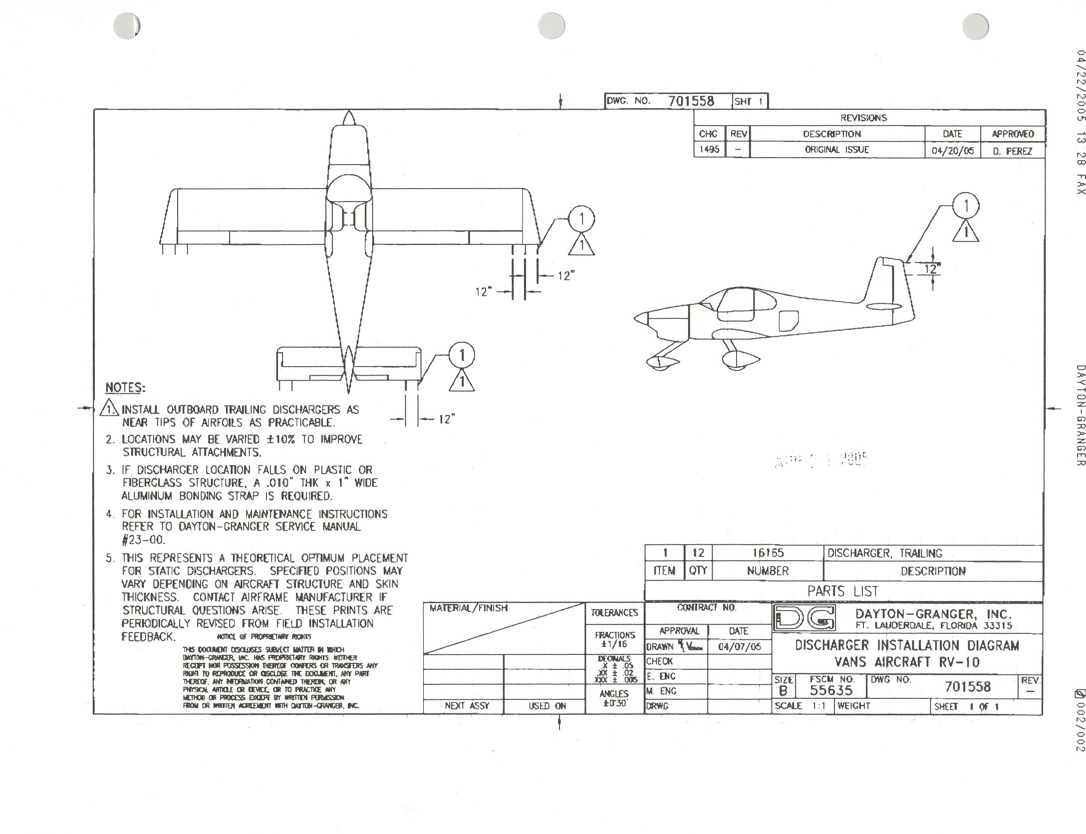
    I started my research by looking at what other builders did, and found the very useful post by Mouser and another similar one by Tim Olson. Both of them used Dayton-Granger 16165, which sounds like a safe bet since Dayton-Granger themselves provide proposed installation instructions specific to the RV10. As much as it would be fun to remember Maxwell's equations to do the electromagnetic calculations myself, I thought I'd trust a company that does this as part of their business :)


    I'm going to follow Mouser's suggested bill of materials, so I ordered the parts for the rudder and elevators:

    The next step is to make sure the electric charge can flow all the way to the wicks. Since I'm priming the parts, the surfaces are not conductive, so I measured the resistance of the skin from distant rivets on and got good results (1-2 ohms). For inter-part conductivity, I mounted one of the rudder attach bolts to the VS and saw that it's a poor conductor, meaning I need to do additional bonding there. The standard way to do bonding is with a braided strap. I also looked at pre-assembled straps with holes (such as this, this, this, this and this), but found that most come in inconvenient lengths and/or hole sizes, so I ended up ordering the braid plus 33457 terminals from Aircraft Spruce.

    To attach the bonding strap to the parts, I'll add a nut plate to both parts (e.g. rudder and vertical stabilizer), for which I picked the same AN366F-1032A nut plate and MS35207-261 screws. The FAA AMT Airframe handbook (chapter 9, figure 9-146) shows the recommended sequence of washers, nuts and their materials for the case where you can install a screw + nut on the same side (but not for using a nut plate). Some more searching found me the Australian AC 21-99 which happens to have that same figure/table (not sure which government copied from which), but also has the equivalent for nut plates (chapter 13, figure/table 13-2):


    Since the braided strap is tinned copper and the structure is aluminum, this gave me (for each bonding / hole pair):
    Now I'm waiting for the parts to arrive, and will make a new post with results afterwards.