Engine sensors, System32, GHA15 and more wiring work

I installed the CHT and oil temperature sensors in the engine:

CHT sensors installed in place

Oil temperature sensor with ATM connector

Oil temperature sensor safetied in place

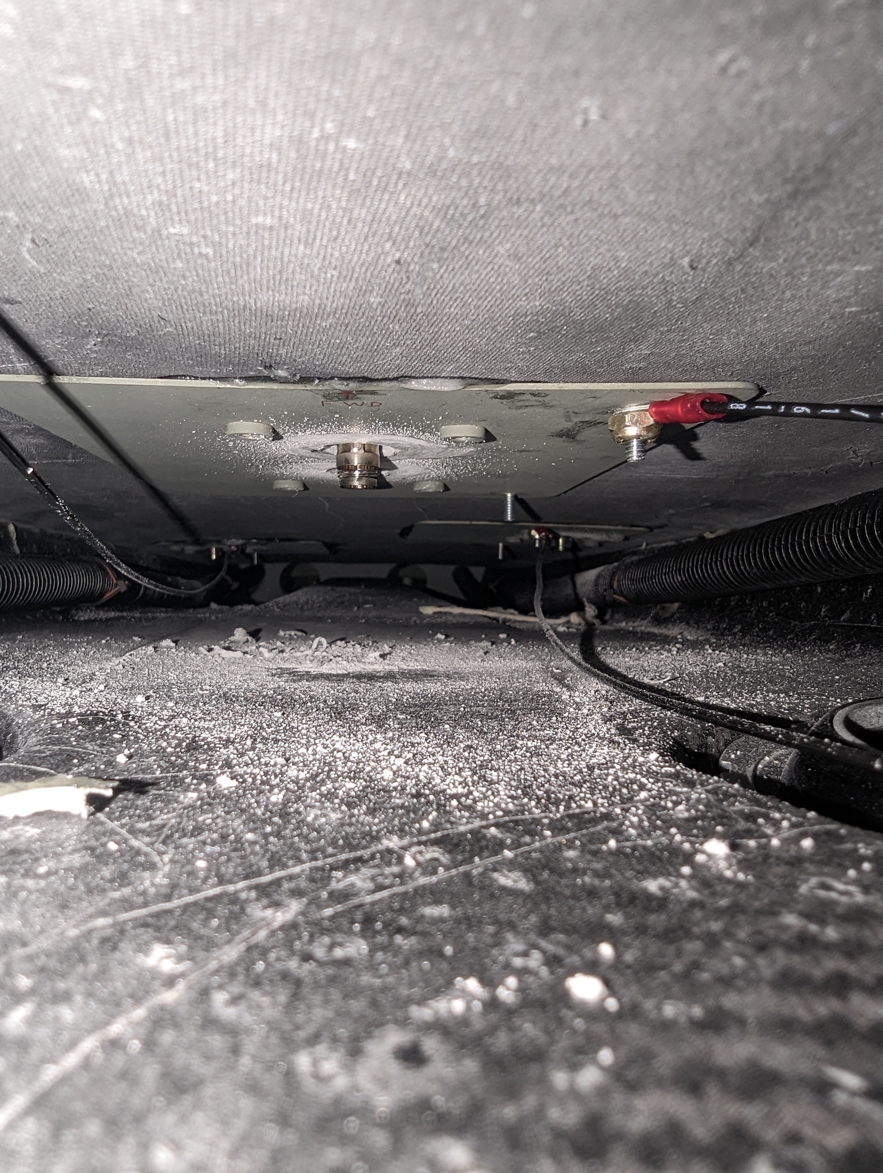
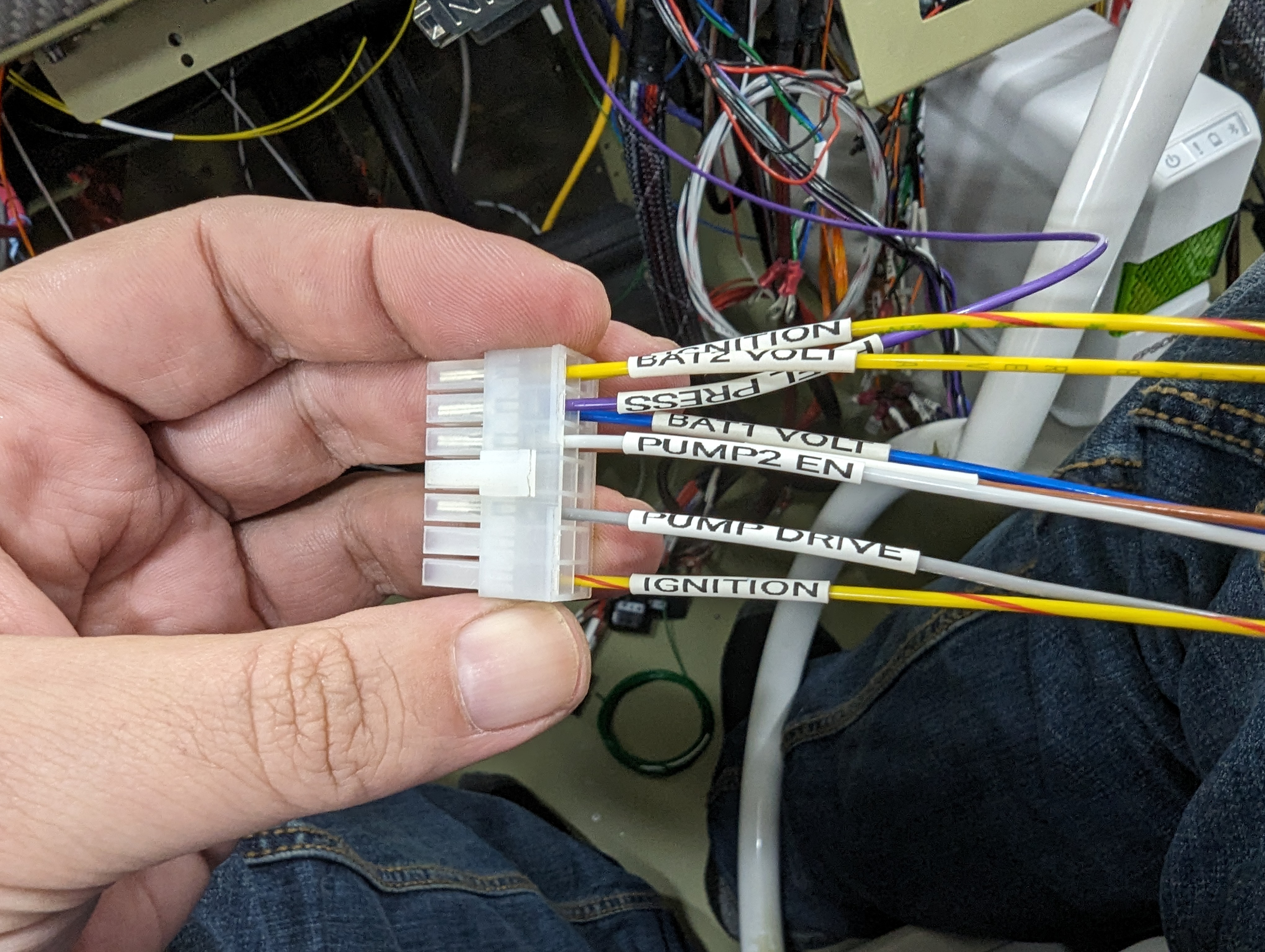
I also finished wiring the System32 (as neatly as I could given its prewired bundles):

Completed ECU wiring in place (bottom view)

Completed ECU wiring in place (side view)

On the main wire bundle, the main challenge with SteinAir making it without having the physical panel is that a lot of the lengths are off - in a couple cases (the GTN bundle and the breakout connectors) it was a bit shorter than I'd like, but in most cases it was too long - like these very generous ground wires and the GEA24 bundle which would hang down onto the copilot's leg:

Super long ground wires I got from Stein, which will need to be trimmed

GEA24 wire bundle hanging down into the copilot leg space

so I shortened the GEA24 by about 8" - luckily, most wires were not connected on the other end so I could just pull them through, but a few others had to be re-pinned. I also realized this is the bundle I'm most likely to make changes to in the future (adding/removing sensors and so on), so I removed the nice-looking sleeving in favor of just wax lacing it:

Shorter GEA24 wire bundle, just wax-laced for ease of future changes

Since I was re-pinning the CAN bus connection to the GEA, I also took the opportunity to add the GHA15 in there, and got started with attaching with its doubler:

Match-drilling the GHA15 doubler in place

GHA15 doubler on the outside for opening up the remaining holes

Yes, the GHA15 is only about 2ft forward of the GA58 antenna, but Garmin doesn't seem very concerned given how far apart the frequencies are (~1GHz at 40W vs 24GHz at 19mW) - worst case, I'll need to adjust positions later by poking more holes into my fuselage. Also, based on the bit of trimming I had to do to the sides of the doubler, I updated the published F360 project so no/little trimming is required.

I also started analyzing the VP-X connections for reliability, and came up with a matrix of what bank I want each device to be on (so a full bank failure leaves me enough on the other bank to keep flying comfortably in IMC). The criteria was:
  • GTN and GNX should be on separate banks (NAV redundancy)
  • GTR and GTN should be on separate banks (COM redundancy)
  • GAD29 should be on the same as the GTN (most useful together)
  • PFD and MFD should be on separate banks (display redundancy)
  • GSU and G5 should be on separate banks (AHRS redundancy)
  • Fans and GTN should be on the same bank (most heat-producing device)
  • GEA and MFD should be on the same bank (most useful together)
  • GMC and GSAs should be on the same bank (most useful together)
  • ALT1 and ALT2 should be on separate banks (alternator redundancy)
  • Landing and recognition lights should be on separate banks (landing light redundancy)
  • IBBS and G5 should be on separate banks (backup battery redundancy)
  • Pitot heat and PFD should be on separate banks (both losing the PFD and getting iced up in IMC would suck)
With that criteria, I came up with a matrix of possibilities (spreadsheet here with a bit of magic in the conditional formatting):


which then let me make the selections:


Next, I'll shorten/move the IBBS wire bundle, wire the EFII display, wire all the switches, and get started on the power wiring updates above.

Time lapse:


Total avionics rivets: 161
Total avionics time: 193.2h

FWF fuel system installed

I replaced the original EFII hoses between the cylinders with the much nicer Aircraft Specialty ones, and attached the hoses to the regulator and post filter:

Original FlyEFII fuel hoses connecting the injectors

Aircraft Specialty integral firesleeve hoses connecting the injectors and regulator

Aircraft Specialty integral firesleeve hoses connecting the injectors and post filter

To use the cross-over hose from AS, I had to thcange the fitting on cylinder 1 to an AN826-6D ($15.50 at Spruce - what happened to hardware prices!?):

AN826 fitting connecting the right forward injector to the cross-over hose

Multiple fittings to connect the left forward injector to the cross-over hose

I'm still puzzles by having to use 3 fittings and a shorter hose on cylinder 2, but they say it's for better fitting the cowl so I believe them. Some day I may change that to another AN826 and a normal-length hose, after I know exactly how the cowl fits there.

Attaching the post filter was quite annoying - I tried the special Adel clamp tool, but the bolt was too short for that, so we ended up developing a new technique for these (which I'm sure someone will say is wrong - but if it worked, is it?) - we compressed the clamps, then ran safety wire at the base of their flange to hold them closed, and with that it was (comparatively) easy to get the bolt and nut in place:
Securing the post filter to the engine mount with Adel clamps


Safety wire trick to tighten the post filter Adel clamps in place

Post filter secured in place

The fuel pressure regulator conveniently had a 1/8" NPT port on the side, so I installed the fuel pressure sensor there:

Fuel pressure regulator with fuel pressure sensor attached

With this, there are only a few finishing steps left for the FWF fuel system - supporting the engine hoses again, adding the induction system drain hole, and securing the cross-over hose.

Time lapse:


Total fuel system rivets: 7
Total fuel system time: 9.3h

Wiring and antenna installation progress

I finally started wiring the EFII system in place. For the ECU RJ45s, I found that 2ft Monoprice cables give me just the right length:

EFII ECUs with shorter CAT5Es attached

I wired the Bus Manager, carefully getting each wire down to the proper length:

Bus Manager with wires attached

Bus Manager right-side wiring

Routing of the Bus Manager wires

EFII power wires in place

I removed the Bus Manager one last time, finished labeling the wires with heat shrink, and then final-attached it in place underneath the ECUs:

Bus Manager with wires attached

EFII ECUs and Bus Manager attached in place

I attached the Noctua fans to the glareshield (had to use 1-1/4" screws, 1" was just slightly too short):

Avionics cooling / defrost fans installed on the glareshield

In the GPS and TAS antenna holes, the core was showing and I wanted to protect + reinforce it, so we filled those sides with resin+flox (and on the TAS hole, used the same resin to attach the 1.5" metal tube section):

GA 57X antenna hole sides showing the core

GA 57X antenna hole sides after covering/reinforcing with resin/flox

TAS antenna hole with resin/flox + metal reinforcement

With that, I attached the GPS antennas temporarily, which made me realize that the screws that came with them are just slightly too short too (they engage the insert threads, but don't come out):

GPS antennas attached to the top of the cabin cover

GA 57X antenna doubler without screws sticking out (meaning they're too short)

Finally, the moment I've all been waiting for - the main wire bundle:

Main wire bundle sitting in the fuselage

I started by loosely attaching it with Adel clamps, then running the side and FWF wires out of the way:

Main wire bundle (somewhat) in place

FWF engine sensor wiring

FWF power and sensor wiring

It was then time to finish wiring the EFII system - for some reason I don't understand, they provide connectors with wires already crimped in them, which is not useful (most of them are too short), so I de-pinned it all and attached my own wires:

System32 pre-wired Bus Manager connector with short wires

In the process, I also realized that their crimps were weird, not really holding the wire jacket (this was true for all pins), which is also against Molex's guidance (in their crimping handbook) of what a good crimp looks like:

System32 pre-wired crimp (left) and mine (right)

Molex crimping handbook highlight showing that the System32 insulation crimps are "marginal"

This was also true about the ECU Molex connectors, so I removed each pin from those, fixed the crimp, and put it back in:

ECU connectors with bad insulation crimps

I attached and labeled all the pins on the Bus Manager first:

Bus Manager connector wiring

Bus Manager connector in place

To avoid having a lot of splices, and because at this point I was a bit annoyed with the provided connectors, I decided to switch the DB25s from soldered to crimped pins, also moving one pin at a time:

Moving ECU soldered DB25 pins to crimped pins

Last but not least, I started the wiring of the Spartan3 (only leaving out the actual wideband output pin since that's already wired on the GEA24 side):

Spartan3 AFR connector wiring

Next I'll finish connecting the EFII and Spartan3 to the main wire bundle, and try to finish other updates to the main bundle.

Time lapse:


Total avionics rivets: 161
Total avionics time: 175.3h