I finally started wiring the EFII system in place. For the ECU RJ45s, I found that 2ft Monoprice cables give me just the right length:
EFII ECUs with shorter CAT5Es attached
I wired the Bus Manager, carefully getting each wire down to the proper length:
Bus Manager with wires attached
Bus Manager right-side wiring
Routing of the Bus Manager wires
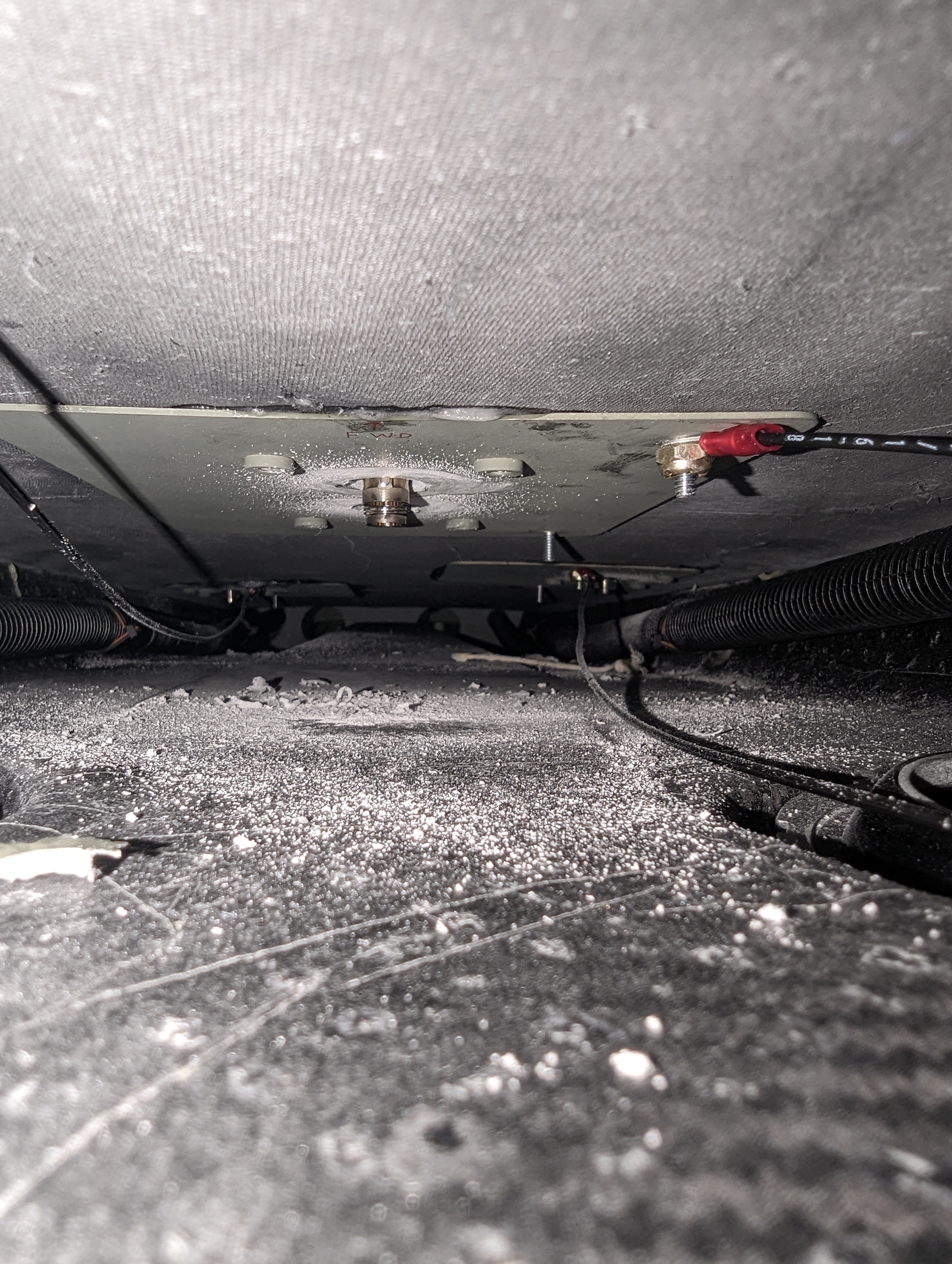
EFII power wires in place
I removed the Bus Manager one last time, finished labeling the wires with heat shrink, and then final-attached it in place underneath the ECUs:
Bus Manager with wires attached
EFII ECUs and Bus Manager attached in place
I attached the Noctua fans to the glareshield (had to use 1-1/4" screws, 1" was just slightly too short):
Avionics cooling / defrost fans installed on the glareshield
In the GPS and TAS antenna holes, the core was showing and I wanted to protect + reinforce it, so we filled those sides with resin+flox (and on the TAS hole, used the same resin to attach the 1.5" metal tube section):
GA 57X antenna hole sides showing the core
GA 57X antenna hole sides after covering/reinforcing with resin/flox
TAS antenna hole with resin/flox + metal reinforcement
With that, I attached the GPS antennas temporarily, which made me realize that the screws that came with them are just slightly too short too (they engage the insert threads, but don't come out):
GPS antennas attached to the top of the cabin cover
GA 57X antenna doubler without screws sticking out (meaning they're too short)
Finally, the moment I've all been waiting for - the main wire bundle:
Main wire bundle sitting in the fuselage
I started by loosely attaching it with Adel clamps, then running the side and FWF wires out of the way:
Main wire bundle (somewhat) in place
FWF engine sensor wiring
FWF power and sensor wiring
It was then time to finish wiring the EFII system - for some reason I don't understand, they provide connectors with wires already crimped in them, which is not useful (most of them are too short), so I de-pinned it all and attached my own wires:
System32 pre-wired Bus Manager connector with short wires
In the process, I also realized that their crimps were weird, not really holding the wire jacket (this was true for all pins), which is also against Molex's guidance (in their crimping handbook) of what a good crimp looks like:
System32 pre-wired crimp (left) and mine (right)
Molex crimping handbook highlight showing that the System32 insulation crimps are "marginal"
This was also true about the ECU Molex connectors, so I removed each pin from those, fixed the crimp, and put it back in:
ECU connectors with bad insulation crimps
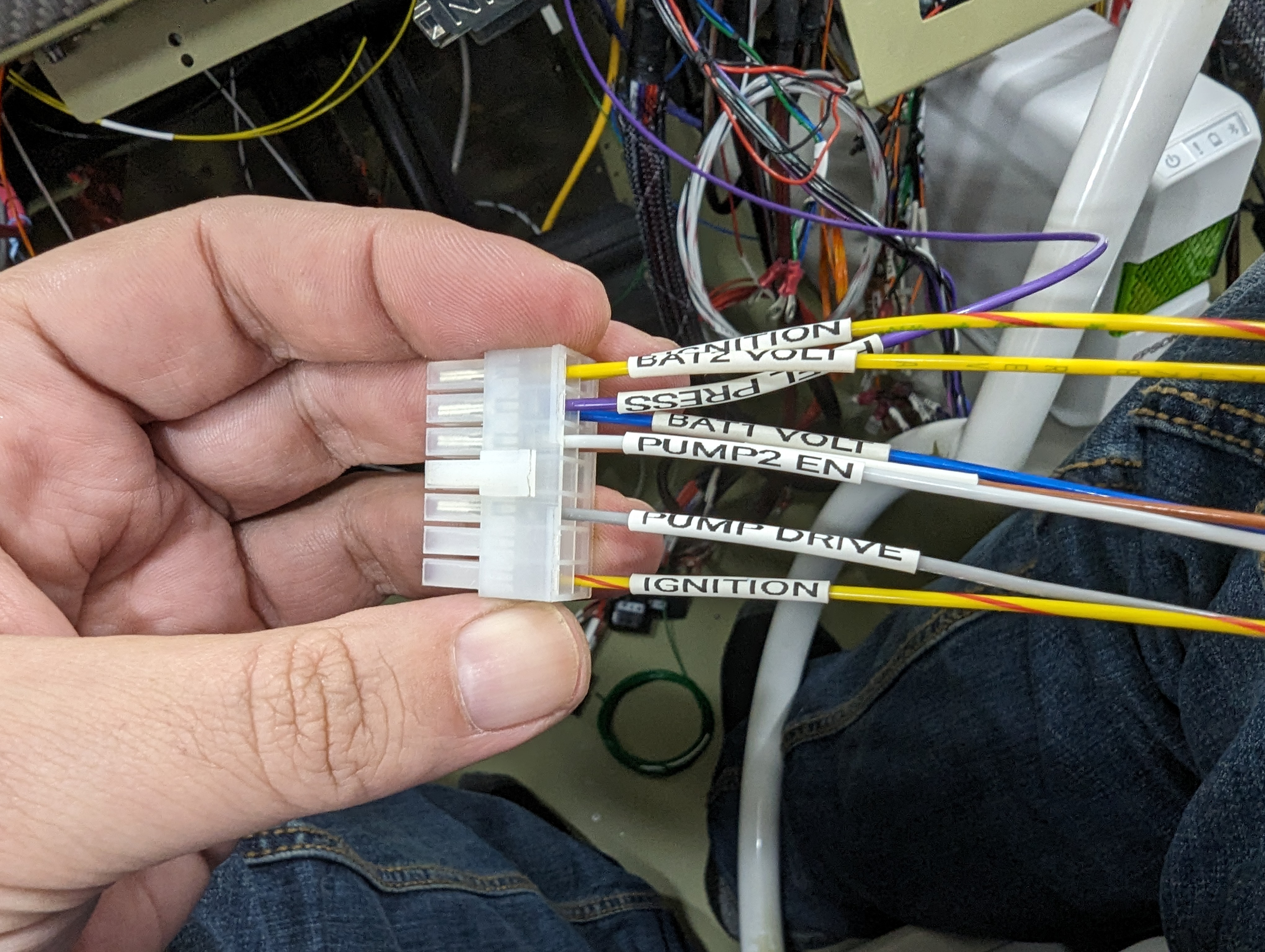
I attached and labeled all the pins on the Bus Manager first:
Bus Manager connector wiring
Bus Manager connector in place
To avoid having a lot of splices, and because at this point I was a bit annoyed with the provided connectors, I decided to switch the DB25s from soldered to crimped pins, also moving one pin at a time:
Moving ECU soldered DB25 pins to crimped pins
Last but not least, I started the wiring of the Spartan3 (only leaving out the actual wideband output pin since that's already wired on the GEA24 side):
Spartan3 AFR connector wiring
Next I'll finish connecting the EFII and Spartan3 to the main wire bundle, and try to finish other updates to the main bundle.


No comments:
Post a Comment