I ran that last remaining ground wire (the 14ga pitot heat ground) through the existing bundle, then connected the defrost fan power/ground crossing above the GTN, to be secured above it in some way (probably a Clickbond?) later along with the G5 GPS cable:
Cooling/defrost fans connected (wire over GTN to be secured later)
For the door sensors, I had previously attached Molex SL connectors to them, not realizing that the 18AWG I had ran for it per plans does not fit in the SL series :( so I swapped those for Molex CP series which can do 18AWG and are still fairly small:
Molex SL series (bottom, black) vs CP series (top, green) attached to door sensors
I ran the wire between the sensors on each side, but I'm still waiting to do the side connectors before I trim the other wires:
Molex CP series connector attached to door sensor
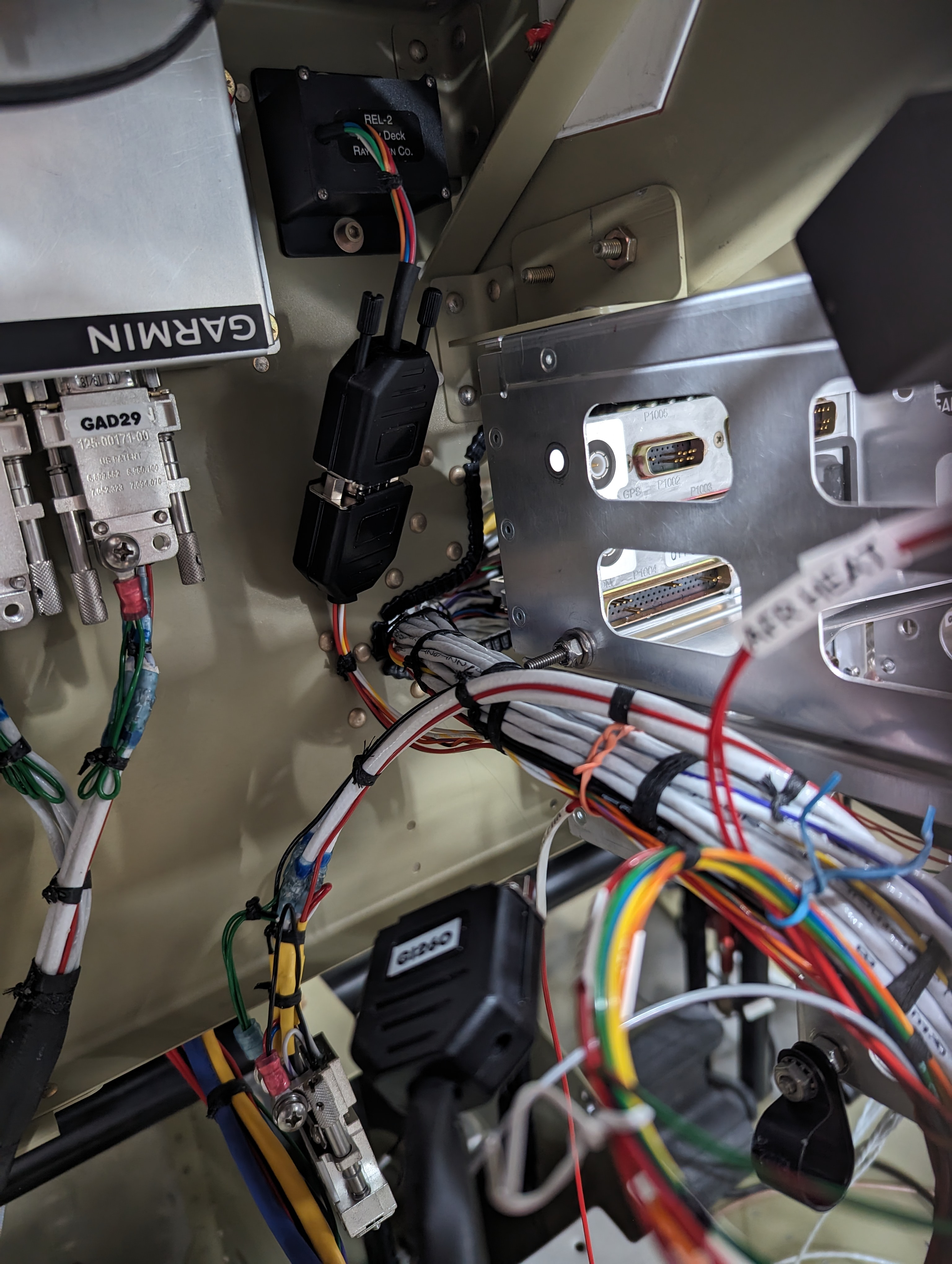
To prevent any chafing of wires coming out of the LRUs against the subpanel edge, I paranoidly added some grommet edging to that:
SL1 edge grommet on subpanel edge to prevent chafing
It was then time to finally work on the side connectors - the plan is to replace most DB connectors with a single CPC, and leave only the roll servo connector as is (so I can plug the CAN terminator to it). I started by trimming all wires to roughly the same length, re-pinning them (the TE series 2 CPCs use M39029/63-368 sockets just like the the DB connectors, so for all wires that were on the shortest bundle, no rework was needed), and adding labels which were missing:
Labels for right-side CPC breakout connector
Right-side breakout wires (including longer GTS power pin)
For the few 18AWG wires (the GTR20 and GTS800 power wires), those pins are too small. Stein's install had the GTR wires spliced onto a 20AWG wire just to go through the connector (and I left that in place since it was already the final length), but they had used a large separate Molex connector for the GTS power and ground - instead of doing that, I used the special 18AWG pin/sockets (FC6018D2 / MC6018D), which are a tradeoff - they require no splice, but they extend outside the connector housing and require heatshrink around the extension, plus they're not removable (the way to remove them is to cut them off since there's no way to get the removal tool around the bulkier part of it). I figured that if I ever do need to remove them, I can then add the splice and use a regular pin.
I then finally installed the CPC - the shell was a tight fit but I didn't need to go to the large-size shell as I had feared:
Right-side breakout connector fully pinned and ready to close
Right-side CPC and roll AP connectors closed up
Right-side CPC and roll AP connectors
Next I'll do the same to make the left-side breakout connector (which is much simpler since that's the power connector, but also much more critical as it'll carry power to the EFII system and feed the essential bus).
I also finished wiring the VP-X by running all the light and pitot heat wires to the wing root exit points, and changing how Wig-wag is connected - in the old Ziptips they had to be grounded, were 18 AWG wires, and were associated with the landing lights, with the new ones they're 22 AWG wires connected to power and associated with the taxi lights, so I ran the wire out of the taxi light output of the VP-X.
I then took on the tedious task of labeling the ground wires (which didn't come labeled from Stein) - which meant getting a probe into each device's ground pin, and then using the other to figure out which ground connector it was wired to, and since there were multiple wires per terminal, then cutting off the connector and figuring out which of those wires were for the device:
Tracing ground wires (multiple per terminal) before cutting off the terminals
Labels for all the ground wires
Labels on all the ground wires after tracing them
I also ran ground wires for the devices that didn't have them yet (fuel pumps, door sensors, GHA15, etc.), and then finally trimmed them all to size and attached faston terminals:
All ground wires shortened, labeled and with fast-on terminals
Ground wires connected to the forest of tabs on the firewall
(there's actually one ground wire left to run - the pitot heat ground - because I didn't have any black 14AWG handy - but I can easily slip that one through the existing wax lacing)
I ran the left-side signal wires through the conduit to the tailcone, connected the relay control wires, and attached terminals to the battery fault and hall effect sensor wires. These will get trimmed up front where I insert the breakout connector:
Primary power control wires in place in the tailcone
Next on the wiring, I'll add the side breakout CPC connectors and route the side wires where it doesn't interfere with the Aerosport panels.
I shortened/moved the IBBS wire bundle (which also needed labeling the wires), the CO detector bundle, and the yaw trim bundle:
Pinning and labeling shortened IBBS wire bundle
Shortened IBBS wire bundle
Original, very long yaw trim relay bundle
Shortened yaw trim relay bundle in place
I also finished the roll servo breakout connector, keeping it as DB15 with the same pinout as the GSA28 itself so that I can directly plug the CAN bus terminator to it:
Roll GSA28 breakout connector with CAN terminator (until the wings are attached)
I then finally wired the EFII display connector and circuit breakers (may still need some cleanup/bundling later):
EFII display and circuit breakers connected to ECUs/power
EFII display and circuit breakers with all wiring in place (still not very organized)
After securing the main bundle to the panel, I wired all the switches:
Left-side switch connectors
and then updated the power connections to reflect both the VP-X bank analysis I mentioned in the previous post and the updates for the Ziptip Vegas (as well as shortening the long bundles):
Shortened left-side VP-X wire bundles
Shortened right-side VP-X wire bundles
VP-X with shortened wire bundles
Unrelated to the wiring, there was a discussion about the 120° clearance cone required for the GHA15, which made me measure it again for my install - it is indeed close to the main gear, but just about clears it - I could increase the clearance a bit by moving the antenna a few inches forward, but that'd require relocating the fuel pumps too (at least moving them up to clear the antenna connector), which I wanted to avoid:
Tip of the GHA15 120° clearance cone near the main gear
Next, I'll finish the power wiring by also shortening the fuse block wires, and all the ground wires (which also need to be labeled, none of them currently are). I decided to not try to shorten the GAD29 wires, but that'll be the only long bundle left. I also need to update some of the light switches for the Vegas ziptips (adding the recognition lights, and moving the wig-wag to the taxi light switch).
With this, I'll be doing the long, tedious work of doing a continuity check on all the in-panel connections (I'll later do the same for the tailcone and overhead connections, once I've finished the breakout connectors) - maybe by the next post I'll be able to turn on some of the avionics again.