I've been going through the sections pretty quickly, it seems (though I've only been doing the fabrication parts, and leaving deburring/primer/riveting for later). Today I got to start Section 28 - Forward fuselage ribs, bulkheads and bottom skin (though I haven't done anything related to the skin yet).
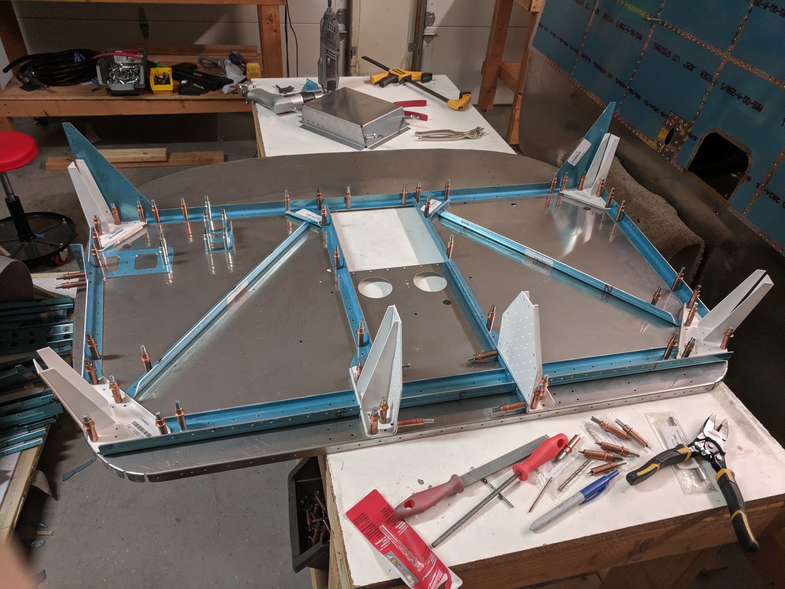
This starts by assembling (mostly with bolts) the bulkhead assemblies, some final-drilling and then match-drilling through the control column mount for more bolts:
Forwad fuselage bulkhead sub-assembly
Both forwad fuselage bulkhead sub-assemblies
This section seems to be longer than most previous ones, so I'll likely have many more posts about it.
Time lapse:
Total forward fuselage ribs, bulkheads and bottom skin time: 4.5h
I started working on the firewall. Since I'm not yet sure about what engine I'll use or what I really need firewall-forward, I'm being conservative on which steps to undertake now.
The first step is assembling the main firewall parts and final-drilling them:
Main firewall parts clecoed and final-drilled
To prepare the firewall recess, the manual suggests dimpling certain holes with a rivet + female dimple die - I did just that, and sure enough, the dimple die was then firmly secured to the recess :p I had to drill out the rivet to actually remove it from the die:
The recess dimpled holes weren't supposed to be attached permanently to the dimple die
Finally, I match-drilled the forward fuselage rib and its parts, then attached them to the firewall bulkhead:
Fuselage ribs and related parts
Firewall with main fuselage ribs attached
Next I need to dimple all the holes on the firewall bulkhead and counter-sink the matching part holes. I also want to research stainless-steel rivets to use on the firewall, and I'm thinking of following the advice of many threads on VAF regarding fire protection, where they use steel foil with fiberflax on the forward side.
We made some progress in wiring the wing, in preparation for riveting the outboard wing skins.
We added holes to the conduits, with bushings for the wires to come out:
Conduit hole with bushing
This was done with a heat gun with a circular tip, for simplicity - melting away the hole seems to be much more reliable in that it's unlikely that a cut will propagate and open up the conduit.
Heat gun for conduit holes
Opening holes in the conduits
Most holes were added near inspection panels (since that's where most equipment will be), except for the pitot heat controller box, which sits adjacent to one of those areas:
I was excited to pick a decent color scheme for the wiring, since so many colors are available, until I found out that most of the wires I'll end up running are shielded, and those are always white (with fixed colors for the inner conductors) :/
Given this, I decided to follow the Aveo colors for the wingtip wires (with one addition - using black/yellow for one of the returns). This is for the right wing, where the servos are - the left wing has antennas and thus gets the shielded equivalent.
We then started running wires:
Autopilot-to-trim-servo wires going through the conduit
For the pitot heat controller, I used 12AWG shielded cable (M27500-12TG2T14) - shielded so the magnetometer and NAV antenna can go on the wingtip without as much interference, and added connectors:
Pitot heat controller wired through conduit
I then ran the controller box wire to the bay where the pitot tube actually is, through the aft conduit Clickbond attachments:
Pitot heat wires going through Clickbond attachments
There'll be a lot more wiring to come, but most of that can be done with the wings closed - the main exception was the pitot heat, which will be much harder to access.