I managed to measure the battery cable lengths I need, and those are on order from Aircraft Specialty. I also drilled nutplate holes for all the subpanel LRUs.
I fabricated the smaller tailcone avionics shelf (mentioned in the previous post) and drilled it for the GTS800 horizontal mount and the WX-500:
 |
| WX-500 (left) and GTS800 (right) mounts on the new tailcone avionics shelf |
For the GTR20, I'm gonna have a modified version of the F-10112-R made to mount it on the side.
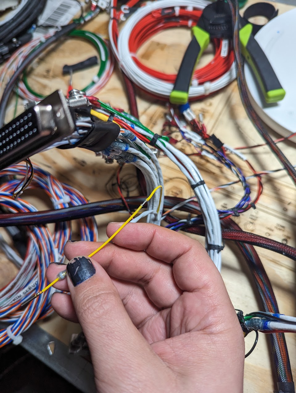
Stein had routed the stick wires to each side (adding splices near the LRU connectors), so I removed the splices and re-routed the wires to the center so I can have a single wire going down the center console and into the tunnel, where I'll install CPCs to attach the sticks. I'll later do the same for the flap wires.
 |
| Stick grip wires coming out of the ~center part of the harness |
They also hadn't wired the GSB15 to the avionics dimmer bus, so I spliced the wire going to the PFD and added that connection:
 |
| PFD dimmer wire stripped at the center |
 |
| Splice on the dimmer wire (not horrible for a first attempt) |
 |
| GSB15 connector with dimmer wire |
I also removed the WX-500 "display clear" and "COM inhibit" wires from the main wire bundle - I have no use for the display clear connection, and COM inhibit is only needed if I see interference from the COM radio (at which point I can just plug it back in).
Finally, I added Molex SL connectors to the reversionary switch and to the cowl flaps switch so I can remove the front panel without having to unscrew those from the panel:
 |
| Molex SL connector on the reversionary switch wires |
 |
| Molex SL connector on cowl flap wires |
I still have quite a bit more surgery to do to the wire harness. Specifically:
- Add all the VP-X wires that need to go aft to the main harness
- Move the taxi light wire from the VP-X J8 to the J10 connector so all lights are coming from the same side of the VP-X (easier to route)
- Splice all the light wires so they can go out to both wings (and probably with the correct color wire, rather than all red)
- Connect the door sensor wires
- Connect the battery fault LEDs
- Move flap motor and position wires into the center bundle
- Redo most of the fuse block wiring
- Move ELT wires into one of the breakout connectors (GTS?)
- Add the wing root breakout connectors
- Route the trim position wires into breakout connectors
- Connect alternator switch wires
- Add the AFR input to the GEA24
- Connect the LED strip properly
Total avionics time: 34.4h
No comments:
Post a Comment