I was planning on adding access panels forward of the windshield anyway (seems to be a common mod), so I was happy that Van's released an official OP kit for this (OP-43). It works pretty much like all access panels - match-drill the doublers, cut the skin, then file it all down until it fits well:
Doublers and covers atop the forward fuselage top skin
Forward fuselage top skin match-drilled for the doublers and marked for cutting
Forward fuselage top skin after cutting, with doublers and cover on
Whenever I do the next batch of primer, I'll include these so I can start riveting them (though I won't prime for rivet the top forward skin for quite some time still).
We started bending the brake lines - it was at first an exercise in patience, and our first attempt was definitely not good :)
Very irregular curve on our first attempt on making the brake line (left), vs a better result on the second (right)
Kink made during our first attempt on making a brake line
We persisted, and the second and third attempts were actually quite decent:
Firewall fittings connected to rigid brake lines
Rigid brake line bends
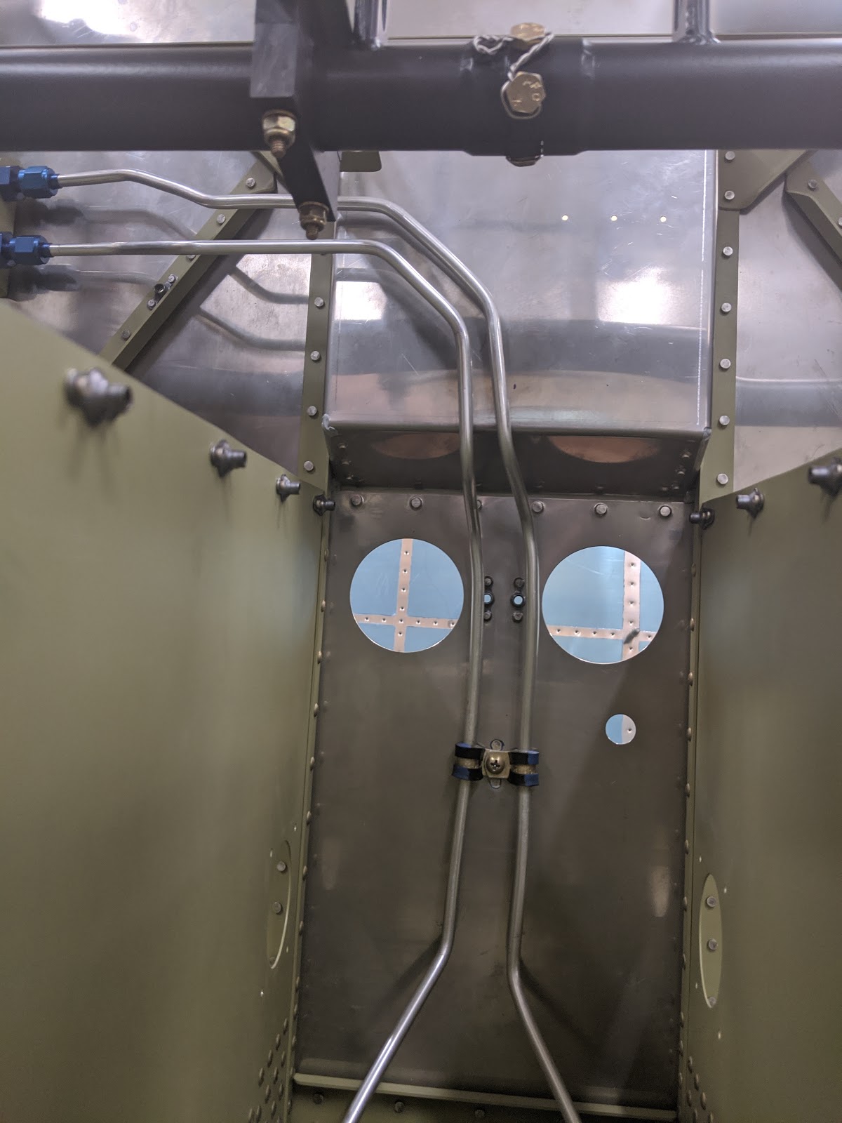
Rigid brake lines going down the firewall
Rigid brake lines going aft through the tunnel
With that done, I dimpled and riveted the ducted flanges to the tunnel:
Ducted flange riveted to the tunnel above the brake lines
For the tunnel-to-gear tubing (as well as the pedal tubing in section 38), I'm just getting the lines made by Aircraft Specialty, plus I need to torque all these fittings, so I'll have a short follow-up, but other than that this section is complete.
Time lapse:
Total brake line rivets: 8 Total brake line time: 6.5h
The next step in the tailcone attachment was, well, to detach it :) so I did:
Tailcone detached from the fuselage
I added the Panduit conduit mounts to the lightening holes:
Match-drilling Panduit conduit mounts to the bulkhead
The sequence here was to attach the tailcone, the baggage/rear seat floors, drill everything needed (e.g. door, floors, covers, etc.) while the cone was attached, then detach it, so that I could do a single larger batch of primer and need less post-primer drilling.
After that batch of primer, I riveted the bulkheads together:
Bulkheads riveted together and to the Panduit conduit mounts, after primer and paint
and attached those to the fuselage - the plans call for attaching it to the tailcone first, but I figured this would be easier since there are more rivets on the baggage rib attachment:
Bulkhead riveted to the baggage ribs
With this, we finally attached the cone for good:
Tailcone clecoed to the fuselage once again
then riveted it:
Left side skin riveted around the baggage door opening
Fuselage and tailcone longerons bolted together
Tailcone (left) and fuselage (right) bottom skins riveted together
About going out of order and it being easier this way - wellll, at the very end, when we got to the part that would normally be done without the fuselage in place, we screwed up badly on one rivet and had to upsize it. We tried setting the surrounding ones but they were starting to look really bad too, so we removed it all and switched to CherryMax (CR3213-4-2, CR3243-4-2 and a CR3243-5-2 depending on the hole):
Enlarged hole from removing a bad rivet :(
That face you make when you badly enlarged a hole while removing the rivet :)
Fixed bellcrank rib attachment, using CherryMax rivets
With this, section 32 is complete!
Time lapse:
Total tailcone attachment rivets: 236 Total tailcone attachment time: 22.8h
I started riveting the baggage area. The nutplate rivets on the upper baggage seal channel were going to be just impossible to buck, so I used Cherry nutplate rivets (CCR series) instead:
Upper baggage seal channel nutplates riveted with cherry rivets
Painted and riveted upper baggage seal channel
I attached nutplates in most places that called for them, except those that would attach them through multiple parts:
Baggage bulkhead corrugations with wear blocks and nutplates on
Rear seat floors with nutplates on (some rivets were replaced after this)
Baggage floor inspection panel doublers with nutplates on
Baggage floors with O2 tank attachment doublers, inspection panel doublers and nutplates on
We then installed the Clickbond mounts for running the conduits underneath the baggage area:
Sanding Clickbond mount attachment areas, protected with tape
Sanded areas for Clickbond mounts
Clickbond mounts attached to bottom skin
All Clickbond mounts attached to bottom skin for conduits
Since we were doing that, we also installed a few of the Clickbond mounts farther forward:
Clickbond mount for running wires into the wing connectors
Clickbond mounts for running wires across the rear seats
One of the Panduit conduit brackets ended up being drilled too low :( so to remedy that without having to drill yet more holes, I made a shim for it:
Panduit conduit bracket and 3D-printed shim
3D-printed shim firmly attached to Panduit bracket
I can't, of course, claim that I got those dimensions right on the first try, so it took a few attempts:
All 8 attempts to get the Panduit shim right
Panduit bracket with shim, riveted in place
Checking conduit clearance with Panduit bracket and shim
Now I'm just waiting for the GripLockTies to attach the conduits, before I rivet the floors for good - once that's done, finishing multiple other sections (like the baggage door) will also be possible.
Time lapse:
Total baggage area rivets: Total baggage area time:
then removed rust from the pedals, rust-converted the interior of the tubes, and assembled them:
Rudder pedals assembled
Safety-wired bolts at the center of the rudder pedals
The holes in Beringer's provided bracket for the ALIR regulator, as expected, did not match the delrin bearing block from ControlApproach, so I duplicated it in .080 aluminum to drill new holes:
Original Beringer ALIR bracket (left) and duplicated one for drilling new holes (right)
Per Beringer's manual, I bent the bracket's tip so it hangs lower than the pedal tubes:
Bent ALIR bracket
I duplicated the regulator holes from the original bracket and checked that they still matched the regulator:
ALIR regulator attached to yet-uncut bent bracket
then match-drilled the ControlApproach block into the other end. One deviation from Berginer's suggestion here is that I'm mounting it outboard, since the ControlApproach pedal arms go inboard:
ALIR regulator and bracket installed underneath the rudder pedal brace
I also match-drilled the Beringer parking brake bracket to the (standard) left pedal bearing block, and switched the -22A bolts on these and the center blocks to -23A to account for the added thickness (even though Beringer's manual for some reason still calls for 22?):
Left bearing block mount plate, bearing block and the Beringer parking brake bracket
And then...I saw this post and the install instructions for the Aircraft Specialty hose kit, and changed my mind :) having the regulator on the right side would require the hose to go from side to side twice, so I decided to instead do a cleaner variation of what they did - to attach the bracket along with the regular bearing block mounting plate, I decided to make a combined part:
Outline of new bearing block mounting plate, combining the arms for mounting the ALIR regulator
Combined bearing block mount plate after rough cutting
Combined bearing block mount plate compared to original parts
Combined bearing block mount plate attached to longeron
Combined bearing block mount plate attached to longeron, bearing block and regulator
This is about the same weight as the original 2 parts (in spite of being .125 vs .080 for the original bracket, since it's also removing duplicate material), and is much simpler and less hacky. I didn't bend the arms this time - as long as I keep the pedal in the aft hole of the delrin block, there's no interference - and if I ever need to move it to the forward hole, then I can bend the arms.
I test-installed the pedals with all this, mostly to measure and try out the hoses:
Pedals installed in place with the combined bracket, regulator and parking brake
Regulator screws showing no interference with the pedal
Regulator showing no interference with the pedal or firewall
I still need to remove the left mount plate and prime it, and I can start looking at hoses - from Beringer's video they seem simple to make, but I have no way to pressure-test them, so I'll likely just order them from Aircraft Specialty or TS.
Time lapse:
Total rudder pedal rivets: 0 Total rudder pedal time: 7.8h