Since I have one of the older Ziptip versions, Aveo has offered to replace my module with one that won't cause interference with the GTN's radio, so I removed those modules (which was pretty simple, but involved removing a pretty hard-to-reach screw) and shipped them to Aveo - we'll see how long they take to return those:
Position of the light module attachment screws, in a tight corner
Ziptip light modules after removal
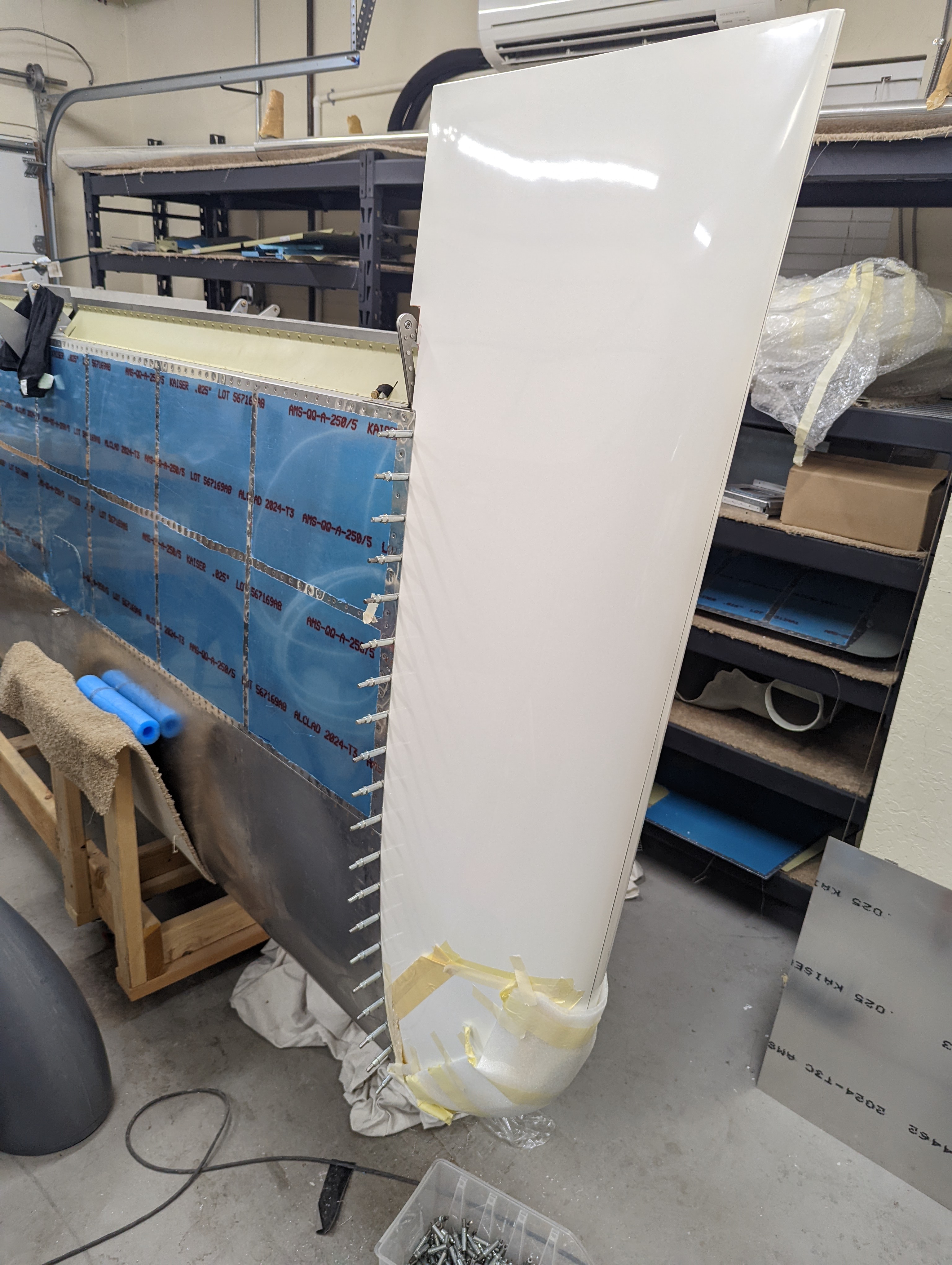
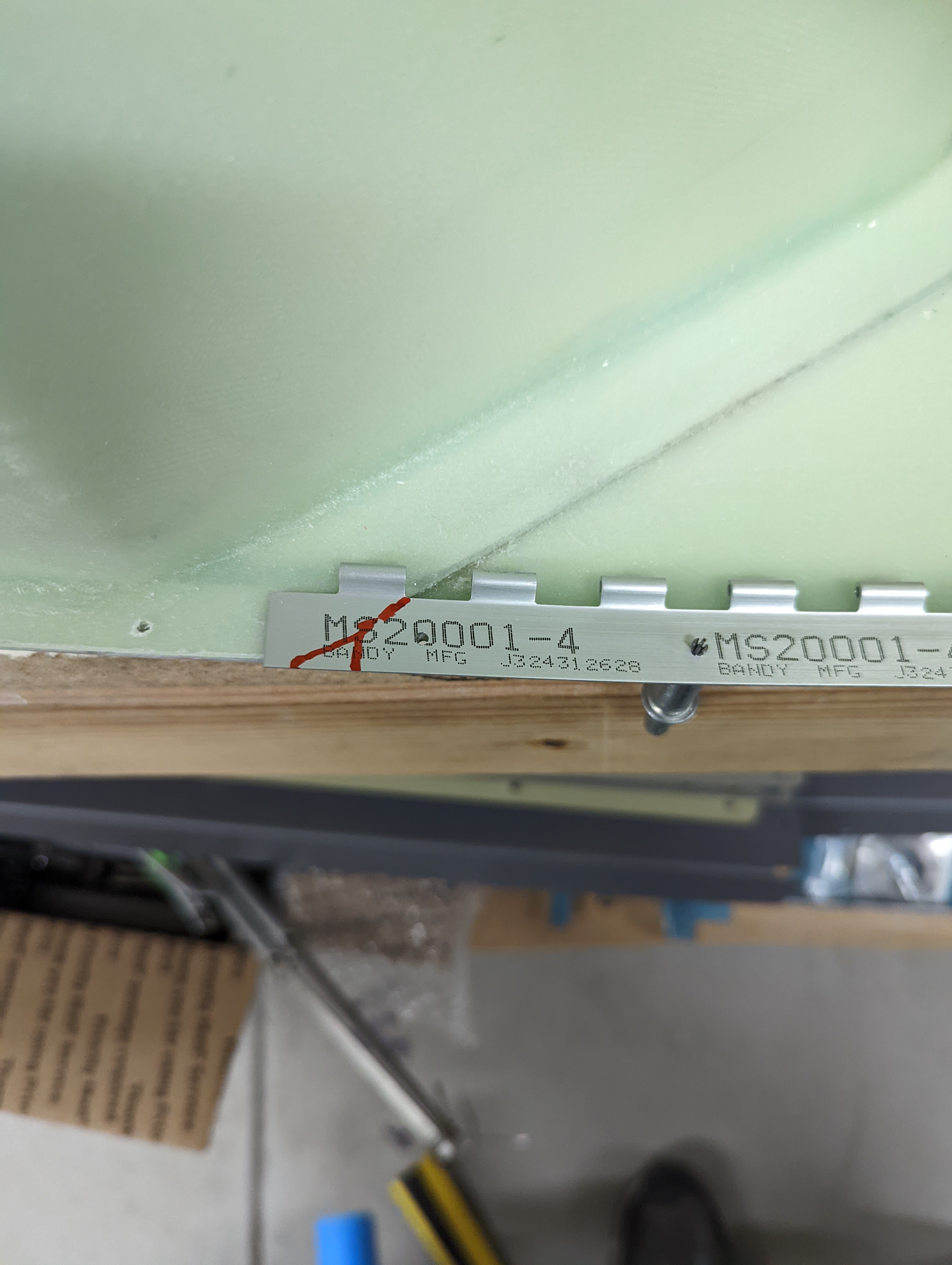
For actually attaching the wingtips, I decided to use the hinge method, which is also described in Tim and Laura's, Mark's family part 1 / part 2, Justin's and Mouser's blogs, as well as a Kitplanes article, using the extruded hinges (MS20001P4) from Spruce. I match-drilled the wingtips into the hinges:
Hinge match-drilled in place
I had to make a small relief/notch on the hinges because one of the J stiffeners was sticking out slightly:
J stiffener that just slightly sticks out beyond the wing tip rib
Also, since the original holes for screws are pretty far apart, I added intermediate holes for the rivets:
Intermediate holes drilled into wingtips and hinges
I also started trimming the wingtips by cutting the flange down to 1/2", which is the width of the skin that sticks out:
Wingtip flange marked for trimming
After this cut, the tips fit nicely on the wings, except that the light module attachment screws were hitting the rib - I used some torque seal to give me the exact interference points, then opened up holes on the ribs to accommodate them (apparently Vans is ok with that):
Torque seal on the light module protrusions
Torque seal markings where the light module protrusions hit the rib
Holes for the light module protrusions
With that, the tips actually fit all the way in, so I match-drilled them as well (which gave me matching holes on the hinges and on the tips:
Wingtip match-drilled into place
Fitting the hinges inside the tips (to match-drill the outboard hinge halves) required a bit of trimming:
Trimming the bottom inboard hinge to fit in the wingtip
Cutout to fit the top inboard hinge
It was also clear that the flange/job was about 0.05" taller than the inner surface of the tips, so to keep the hinges laying flat, I extended that by laying some fiber:
Fiber to extend the top wingtip flange
Fiber laid up to extend the top wingtip flange
Fiber layers for the bottom wingtip flange
With this, I finally clecoed and match-drilled the hinges:
Bottom hinge match-drilled into the wingtip
The next stripping step was to remove most of the flange where the inboard half of the hinges will sit (I had only kept it to have a reference for drilling). I didn't want the hinge showing up, so to keep a small bit of the jog I added some space beyond the edge, and made spacers for the inboard hinge that are slightly smaller than the 0.5" skin, leaving a small slot that the tip can fit into:
Trim lines giving some space to fit into the slot under the hinges
Spacers match-drilled to the hinges and machine-countersunk
Hinges with spacers in place on the wingtip
Next I have to add the same spacer to the other side of the right wingtip, and repeat the whole thing for the left (while also including the Bob Archer antenna).
I started the fuel system by making the TCW fitting spacers actually fit against the wing root fairing support - by trimming that support down to the hole edge, and then trimming the spacer to fit:
Wing root fairing support trimmed down to the fuel fitting hole
TCW spacer trimmed down to the wing root fairing edge
For the other spacers, Vans provided 6 of them, so I had to make another 2 (by just copying one of the 6), then I deburred and primed all of them:
Fuel fitting spacers (6 from Vans, 2 that I made)
All fuel fitting hardware ready to install
I drilled the firewall fuel return hole:
Firewall with an additional hole for fuel return
I also received the super-nice-looking hose kit from Aircraft Specialty, with the integral firesleeves for the FWF portion:
Aircraft Specialty hose unboxing
Aircraft specialty cabin hoses
I then installed all the cabin hoses that didn't require having the EFII system (which I'm still waiting for along with the engine itself):
Hoses installed under the seat
Fuel valve with hoses attached
Tightening the fuel valve fittings with Loctite 648
Valve with tightened fittings and (untightened) hoses
Valve with bracket center attached for installation
Actually attaching and torquing the hoses was actually a bit of work, given I had skipped ahead and done most of section 39 before - this would've been much easier without the pushrod in the way:
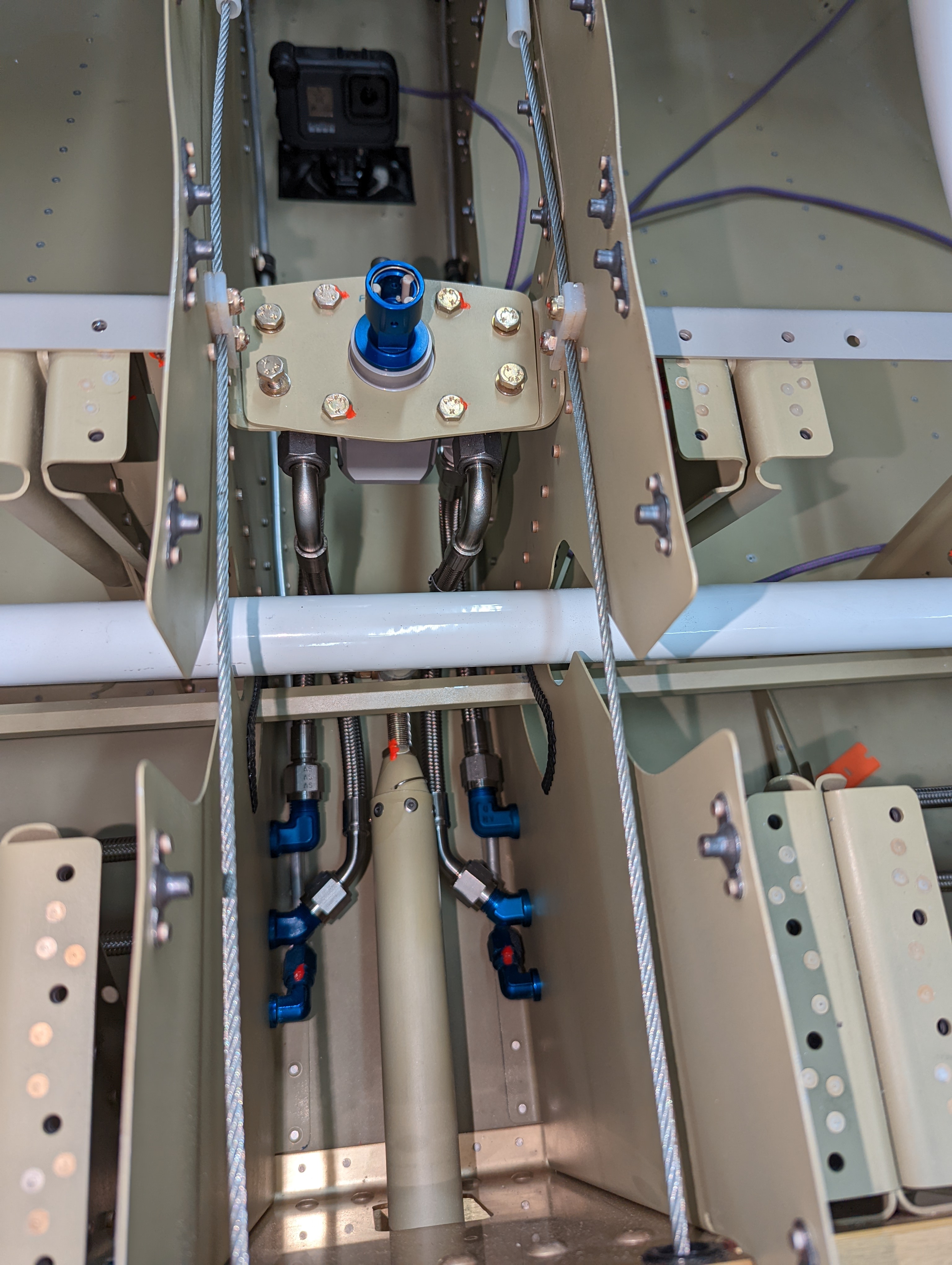
Fuel valve and hoses attached inside the tunnel
There was one small clearance issue, where I had to make sure to tighten a hose out of the way of the pushrod bolt/nut, but I'm not sure if this is a real issue after the elevators are attached, or if it just never moves this far forward:
Clearance between the elevator pushrod bolt/but and the left fuel supply hose
The rest of this section will involve installing the fuel pump hoses in the tunnel, and the fuel valve handle onto the center console.
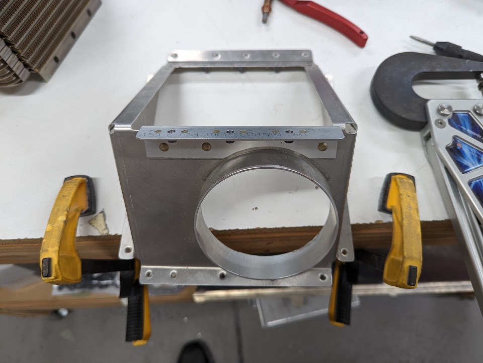
I started section FF1 even before having the FWF kit by assembling the oil cooler box (which I got along with the finish kit).
Oil cooler clecoed to itself
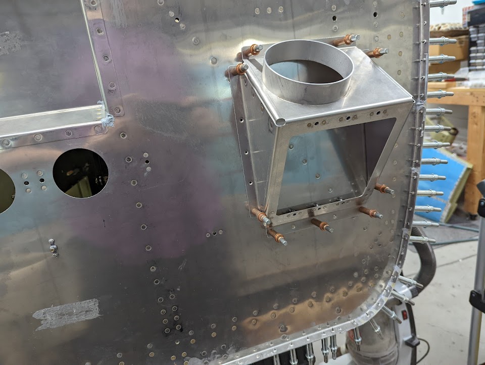
Riveted oil cooler, clecoed to the firewall
I went with one size higher for the actual cooler - the Airflow Systems 2007X instead of 2006X - so I had to modify the mount to fit, by removing the top row of nutplates and attaching them to an angle instead:
Oil cooler mount on top of the oil cooler, for measuring hole positions
Trimmed aluminum angle for attaching nutplates to the top of the oil cooler mount
Oil cooler mount with nutplates on an angle on top of it
Then, per Airflow's instructions, I added a tuning vane to reduce the air pressure difference between the two halves of the cooler, and attached it in place with angles:
Adjusting the tuning vane's position to the center of both openings
Tuning vane with angles for attachment
Tuning vane riveted inside the oil cooler mount using angles
Tuning vane riveted inside the oil cooler mount
Now I'm back to waiting for the engine to arrive before I can continue this section (I've already ordered it from Barrett, a few months ago before the price increases :) ).
I made progress on the EDS-4IP cylinder install, first by attaching the brackets:
O2 cylinder mount brackets and straps in place
I got the loaner O2 cylinder from MH, and checked that it was properly aligned - but also realized I had the wrong metal straps, so I'm exchanging those for shorter ones:
Mountain High O2 cylinder strapped in place
I designed a box to protect it (and even allow lightweight items to be on top), and had it laser-cut and CNC-bent:
Laser-cut, CNC-bent parts upon arrival from SCS
That almost fit well, but was too close up against the rear seat, and made me realize I had a twist in the right baggage cover that needed to be accounted for in the design:
First version of the O2 box, sitting in a tight fit
Significant angle difference on top cover of the O2 box due to twisting
Small gap at the aft portion of the O2 box
Tight fit of the O2 box against the rear seat
Also, the company that CNC-bent them for me apparently doesn't have enough precision for making matching parts (I asked, they basically said that's how it is), so for the second iteration I switched to Oshcut, which was a bit more expensive, but parts were spot on:
Misaligned holes made by SendCutSend
Space inside the box for the cylinder attachment
Second version of the O2 box sitting in place
that was almost perfect, except I forgot to account for the different thicknesses, leaving a tiny gap - so I adjusted again and got just the front lid done again, which fixed it.
Much smaller gap on version 2 of the O2 box
I then match-drilled the box onto the right baggage cover, drilled for nutplates on the cover, and deburred everything:
O2 box (version 3) match-drilled into place
Right baggage cover drilled for nutplates to attach the O2 box
Last on the box, I added a couple of stiffener ribs to support a little bit of weight on top - I made sure to position them away from the attachment straps:
O2 box ribs match-drilled into place
On another baggage area leftover item, I had one rivet left to attach the upper baggage door seal channel, which unfortunately required removing the bolts that join the longerons together - since I had the top forward tailcone skin off, I remove them and set the rivet:
Last, hard-to-reach rivet attaching the upper baggage door seal channel
Next will be applying primer on the O2 box parts and riveting it all together.