I started my research by looking at what other builders did, and found the very useful post by Mouser and another similar one by Tim Olson. Both of them used Dayton-Granger 16165, which sounds like a safe bet since Dayton-Granger themselves provide proposed installation instructions specific to the RV10. As much as it would be fun to remember Maxwell's equations to do the electromagnetic calculations myself, I thought I'd trust a company that does this as part of their business :)
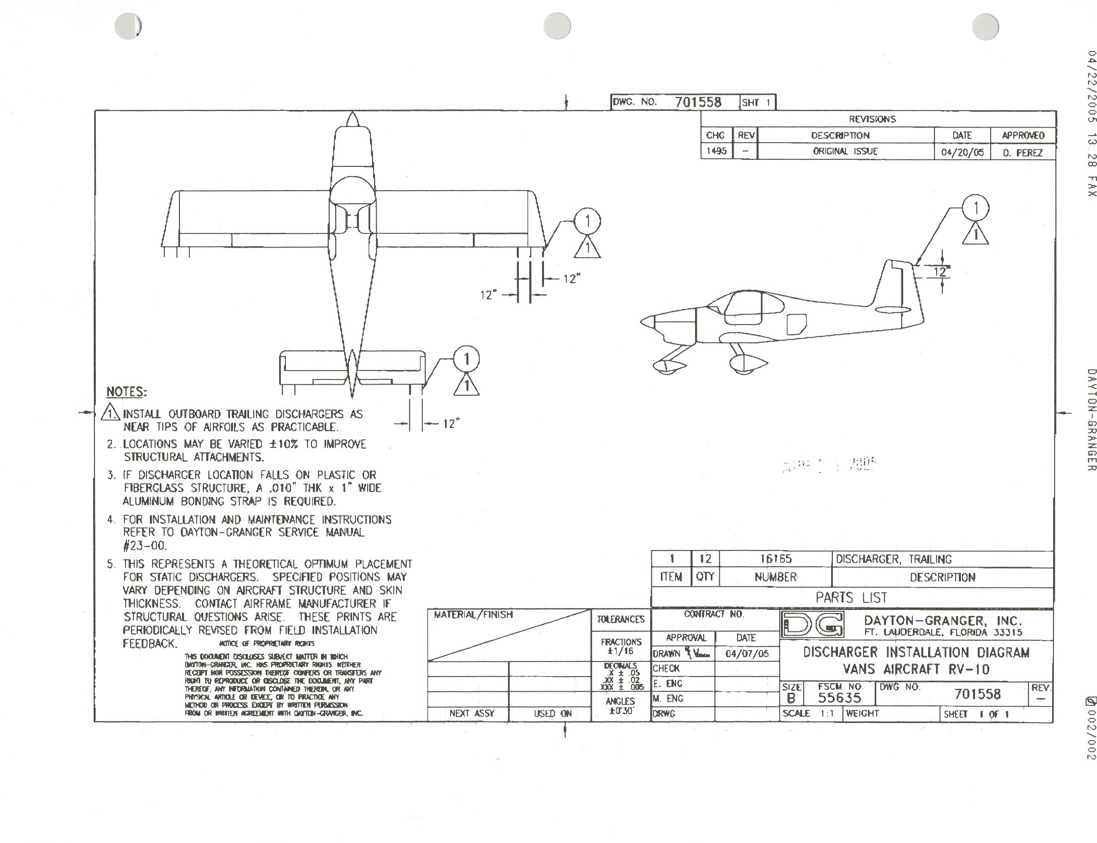
- 6 Dayton-Granger 16165 static wicks
- 12 MS35207-261 screws (equivalent to AN515-10R6)
- 8 AN366F-1032A nut plates (the inboard elevator mounts use 2, the others use 1)
- 4 MS21080-3 one-lug nut plates for the aft rudder and elevator outboard screws
The next step is to make sure the electric charge can flow all the way to the wicks. Since I'm priming the parts, the surfaces are not conductive, so I measured the resistance of the skin from distant rivets on and got good results (1-2 ohms). For inter-part conductivity, I mounted one of the rudder attach bolts to the VS and saw that it's a poor conductor, meaning I need to do additional bonding there. The standard way to do bonding is with a braided strap. I also looked at pre-assembled straps with holes (such as this, this, this, this and this), but found that most come in inconvenient lengths and/or hole sizes, so I ended up ordering the braid plus 33457 terminals from Aircraft Spruce.
To attach the bonding strap to the parts, I'll add a nut plate to both parts (e.g. rudder and vertical stabilizer), for which I picked the same AN366F-1032A nut plate and MS35207-261 screws. The FAA AMT Airframe handbook (chapter 9, figure 9-146) shows the recommended sequence of washers, nuts and their materials for the case where you can install a screw + nut on the same side (but not for using a nut plate). Some more searching found me the Australian AC 21-99 which happens to have that same figure/table (not sure which government copied from which), but also has the equivalent for nut plates (chapter 13, figure/table 13-2):

Since the braided strap is tinned copper and the structure is aluminum, this gave me (for each bonding / hole pair):
- 2 MS35207-261 screws (cadmium-plated steel, same as for the static wicks)
- 2 MS35338-43 lockwashers (cadmium-plated steel) - options where the MS35338 or the MS35335, but since the Australian document mentions the MS35338 several times, I picked that
- 2 AN960-10L / NAS1149F0332P washers (cadmium-plated steel, for washer A)
- 2 AN960JD10L / NAS1149D0332J washers (aluminum, for washer B). The FAA AMT book mentions the AN960JD10L as a suggestion, and I was tempted to replace these by AN960PD10L available at Spruce, but a quick look at the coating codes shows that J is MIL-C-5541 class 3 and P is MIL-C-5541 class 1A - according to the MIL-C-5541 standard, class 3 is really what I want ("where lower electrical resistance is required")
- 2 33457 terminals (tinned copper)
- Tinned copper braid - I ordered a few different sizes and will see which one fits better.
Now I'm waiting for the parts to arrive, and will make a new post with results afterwards.
Hey, awesome writeup. Did you end up stripping away the primer underneath the static wick nutplates before riveting them? I haven't seen anyone call this out, but it must be required to get conductivity.
ReplyDeleteThere was no need, for a few reasons:
Delete- the outside of the skin is not primed, so there's direct contact between the static wick and the skin (and I can keep that contact by not priming/painting/putting vinyl on that portion)
- before doing this I experimented a bunch with an ohmeter on various parts, including nutplates, and found that the resistance across riveted nutplates is quite low (by measuring from the top of a screw attached to a nutplate and another rivet on the opposite side of the part)
- all the holes for these nut plates were drilled after priming, on purpose to increase contact
YMMV depending on the type of primer you use and how thick you apply it, too, so I'd suggest experimenting with measuring the resistance across your parts.