Flap system done

With the last bit of section 26 out of the way, I completed section 40 by actually installing the flap motor. This required some trimming of the angles so the motor doesn't interfere with them when it moves:

PH flap motor brackets put together temporarily

A test run of the motor showed only minor adjustment needed to the rod end, and it was exciting to see something moving in the plane:


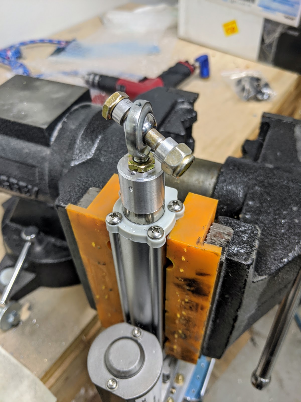
I made the spacers for attaching the motor rod end, and drilled the safety-wire hole at its tip (not strictly necessary since the tip doesn't try to rotate/disengage the bearing like the stock motor does, but it's added safety anyway):

Spacers for attaching motor rod end
Safety wire hole drilled through actuator head

Actuator head with attachment hardware


Finally, I picked the proper spacers from aluminumspacers.com for the motor - I ordered pairs of a few different sizes, but ended up using the 5/16" ID / 1/2" OD / 15/32" long ones:

Spacers for attaching motor

With this, I'm now going to sell the original flap motor (any takers?):

Stock vs PH flap motor

To actually install the flap motor, I also had to secure the TAS cable around it, which I started by running the cable to check its path:

Running TAS antenna cable near flap torque tube

TAS antenna cable running through tunnel around flap motor area

TAS antenna cable reaching antenna, with connectors in position

This was not good enough to understand the cable bends and overall path, so I actually crimped one of the connectors to it:
Stripped RG-400 for QMA connector

Crimped QMA connector

Inner QMA connector conductor, which needs to be soldered

Using that one cable (and the other 3 connectors) to see a realistic cable path, we installed the Clickbond fasteners along the cable's route, and checked that it won't interfere with the pushrod:

Clickbond fasteners installed in place for TAS antenna cables

TAS antenna cable temporarily secured to Clickbond fasteners around tunnel

TAS antenna cable temporarily secured and connected to antenna underneath pushrod

TAS antenna cable connected to antenna underneath pushrod

TAS antenna cable connected to antenna's far-end connector

TAS antenna cable secured to avoid flap crank

We were also wondering if it was ok to mount the control systems and flap motor at this time and still be able to install the antenna later, so we tried a mock install - turns out we can pass the cables out the hole, connect 3 of the 4 to the antenna and still get it back in place, with the last one being the only one that has to be connected through a tiny space around the flap motor and pushrod:

4 TAS antenna cables running through tunnel

Checking if the TAS antenna connectors can be secured from the outside

With this, after completing a large chunk of section 39, I finally installed the flap motor, mostly completing this section:

Flap motor installed in place

I'm leaving the final torquing of those last bolts, the safety wire and running the motor cable for later just in case I need to remove the motor to attach anything else in this busy section of the tunnel.

Time lapse:


Total flap system rivets: 0
Total flap system time: 20.2h

Right door fitting and Aerosport latch assembly

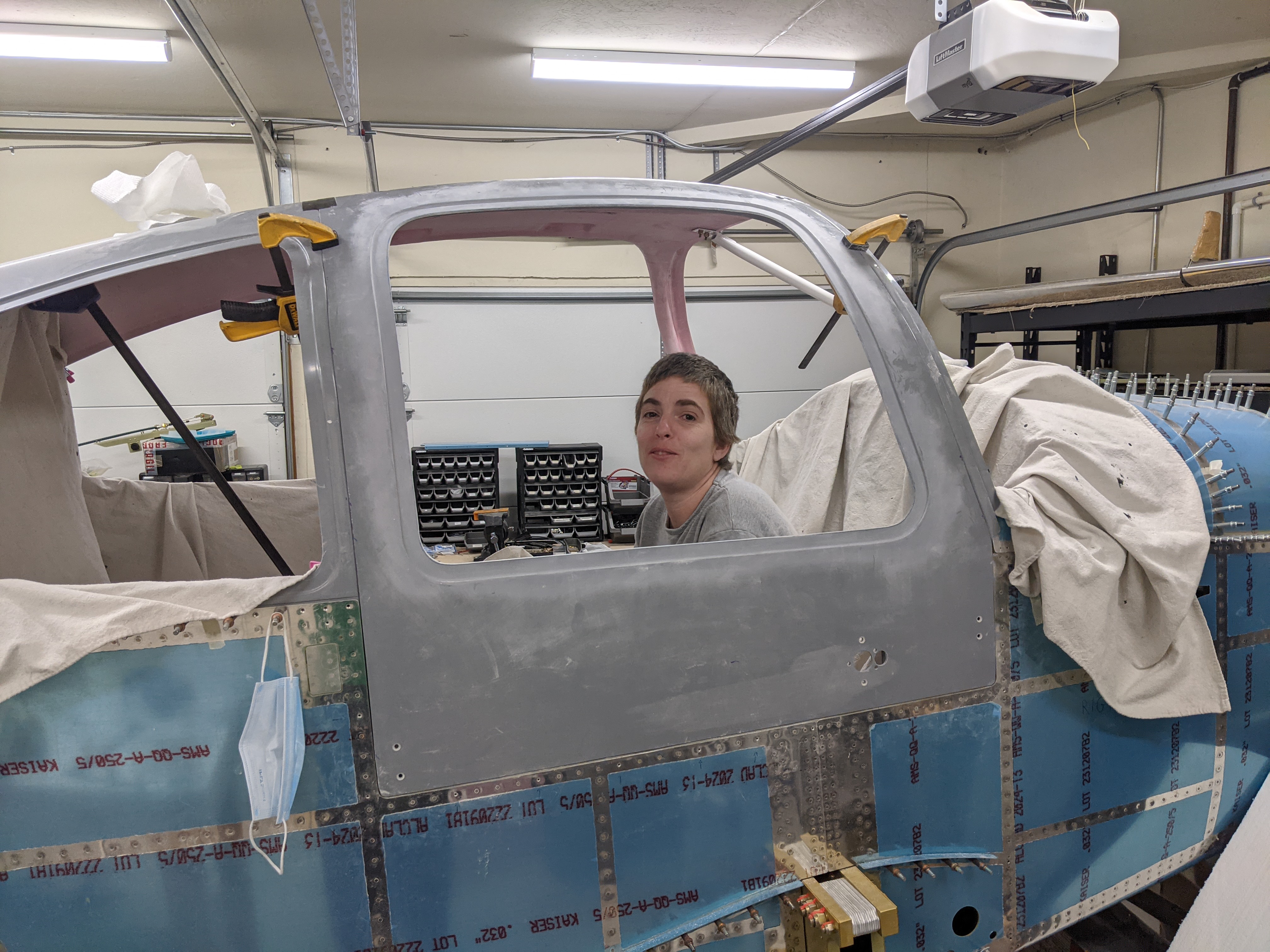
After a LOT more sanding of the right door edges (OMG will the sanding ever end?), we got to the point where they fit reasonably well within the cabin cover:

Lower aft corner of the door, sitting flush with the fuselage

Lower forward corner of the door, sitting flush with the fuselage

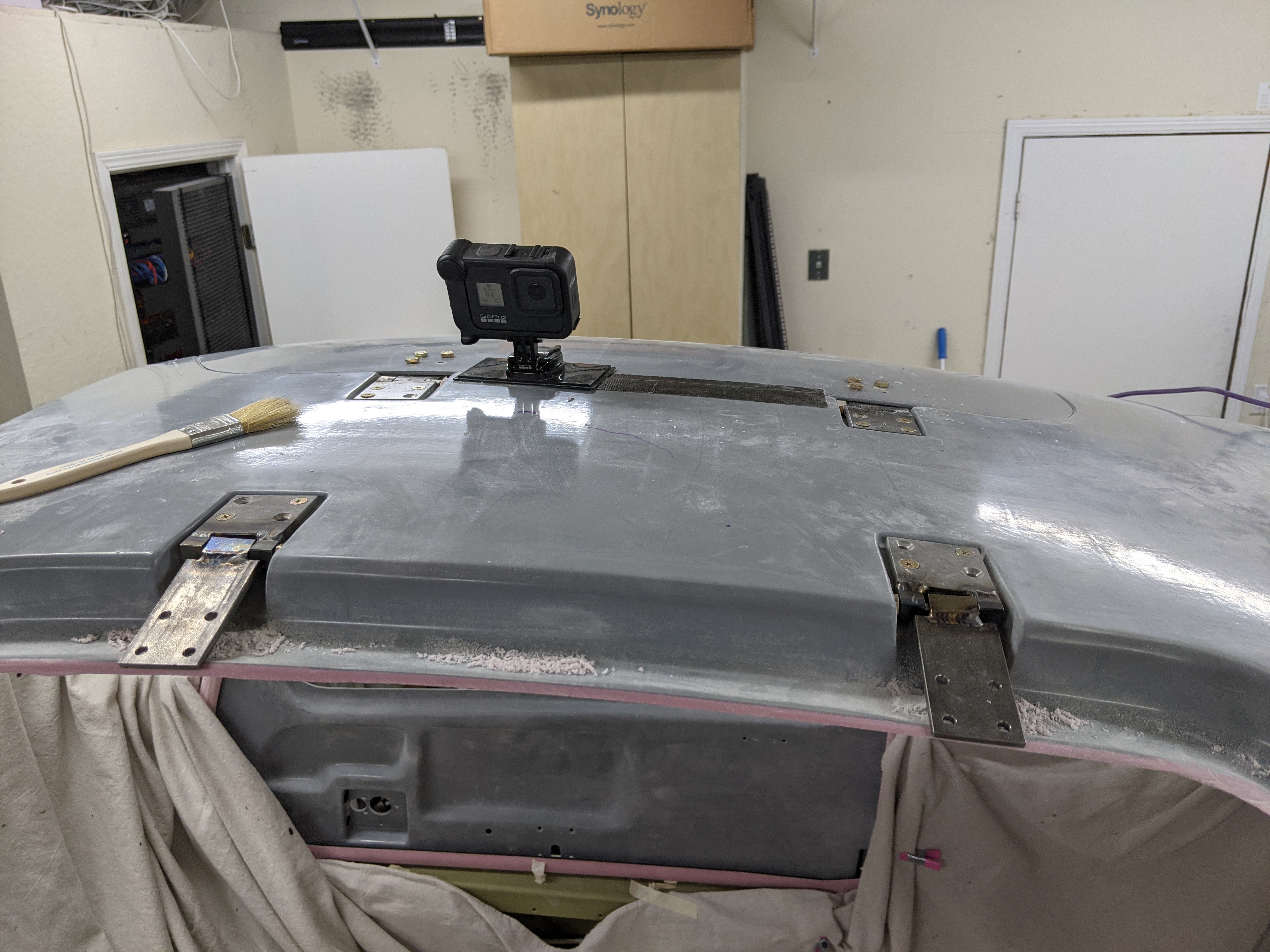
It was then time to attach the hinges. The parts were WD-1018-L/R and WD-1019-L/R, and the plans are slightly confusing about what "L" and "R" mean - they show L and R on the left door, but then no hint as to whether the right door is a mirror or the same. Facebook rescued me (they're the same - R is forward on the passenger side and aft on the pilot side), so I made 1/8" shims and drilled them into place:

Labeled door hinges

Door hinge positioning shims

Door hinge in position for drilling

Door hinges attached to cabin cover

With the door in place, we finally match-drilled the hinges into it:

Door trimmed to fit sitting in the cabin cover

Preparing to match-drill the hinges to the door

Door swung open on its hinges

Hinges bolted to the door

Door sitting flush with the cabin cover

I also got to work on assembling the handle/latch mechanism (for which Ed's video is extremely helpful, except they mount the e-ring on the opposite side - seems to be an older version of the same kit?):

Door handle plates with nutplates riveted 

Handle aseembly with handle plates, spur gear and Aerosport inner ring

Handle mechanism attached to delrin spacer, strike plate, lock and cam

Trimmed lock cam to rotate freely

With this, the handle and lock mechanisms work!


Finally, I trimmed the openings and edges of the Aerosport door handle cover a bit, to fit better and to not interfere with the latch spring when mounted:

Enlarged handle cover hole to not interfere with spring

Some additional trimming of the covers will still be required to fit the lock.

Now on to repeat all the cutting and sanding for the other door...

Time lapse:


Total cabin door rivets: 40
Total cabin door time: 84.9h

Door trimming progress

I did the initial trimming of the edges of both doors with the Dremel:

Trimming off outside door edges

All door edges trimmed off

Then started the real journey of fitting the doors - I started by making small notches with the Dremel, slowly making them deeper until I reached inner surface of the cabin cover all around the door:

Notches around door to find proper trimming depth

Door in place after initial trimming

After this I trimmed off the index hole "flaps", and now I have a TON more sanding/trimming ahead to get the doors to actually fit in the cabin cover. Sand, try it on, still doesn't fit, take it off, rinse, repeat - that's my life now :)

In the meantime, I also 3D printed the door strut placeholder, which will be used for drilling the gas strut attach brackets into the door:

3D printed gas struct placeholder next to the actual gas strut

Time lapse:


Total cabin door rivets: 32
Total cabin door time: 69.6h

Baggage door mostly completed

With the baggage floors riveted on, I moved to the next section, riveted the door hinge frame, and attached the door (using the split pin mod that others have also used):

Baggage door installed in place

Door attach pin, split in the middle and folded into the door

Baggage door strike plate


Door seal applied around the door borders


The only thing left on this section is to attach the left baggage cover, which I'll do later along with the section 35 panels.

Time lapse: 


Total baggage door rivets: 173
Total baggage door time: 14.3h

Rear seat floors and mid seat rails installed

Along with installing the baggage floors, I also installed the rear seat floors. I started by painting the seat belt attachment points, which I hadn't before for some reason:

Painting the protruding rear seat belt attachment points

Then protecting the conduit hole so the conduits don't get damaged by the edges:

Grommet edging to protect the rear seat floor conduit hole

And finally, actually riveting the floors, which was kind of annoying to do without getting inside the plane (which I'm avoiding since it's still on sawhorses):

Riveting the rear seat floors

Riveted rear seat floors

The mid seat rail support doesn't really have attachment instructions (an omission in the manual), but since this section calls for installing the seat floors over them, I also installed them at this time - they were a royal pain to get bolted down and torqued, and required 3 hands and a lot of contortionism:

Mid seat rail installed in place

I'm starting to look at my interior options so I can work on the other cover panels.


Time lapse: 


Total access cover and floor panel rivets: 516
Total access cover and floor panel time: 31.7h