I pulled most wires through the wing root openings, and trimmed some of them:
Wires coming out of the wing root openings, some of them very long
I ran the trimmed part of the GMU bundle through the wing (I'll adjust its length much later when I actually attach the GMU to the wingtip):
GMU wire bundle coming out into the wingtip
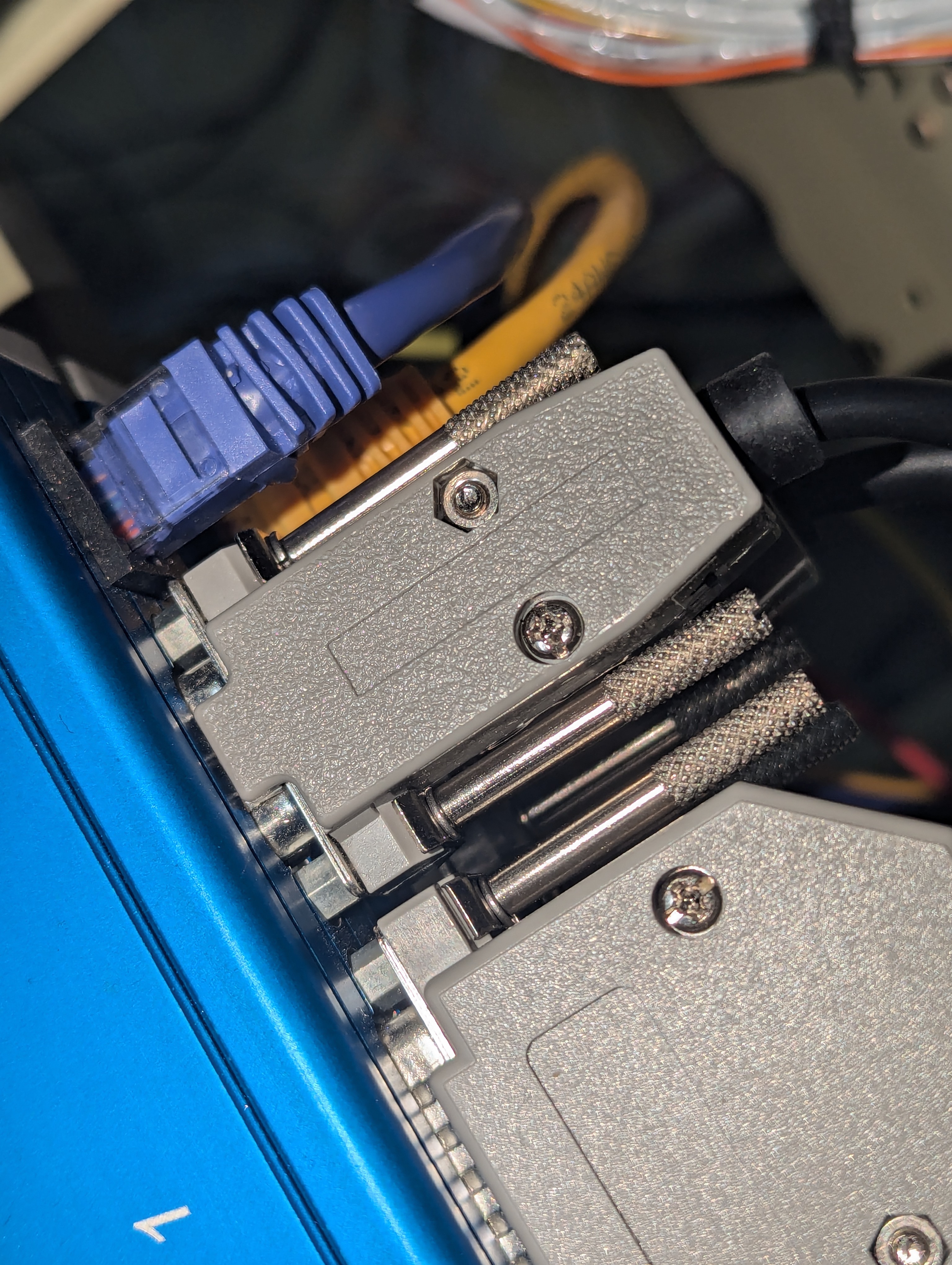
I had previously (~7 years ago) attached a circular connector to the roll trim servo, which was very bulky - I decided to replace it with a much smaller Molex SL connector, and terminated the wing side of those wires to connect it:
Roll trim servo with "mini" CPC connector
Roll trim servo with Molex SL connector
Roll trim servo connector in the wing
On the ECU connectors, I noticed the connectors had some slack because the thumb screws were bottoming out on the holes before fully seating the connectors, so I added some #4 washers to those (which was unfortunately a pain since the wiring was all secured in place already):
EFII ECU connectors with slack between thumb screw and the connector
EFIS ECU connectors after adding lock washers under the thumb screws
We then attached Clickbonds to secure various wire bundles - within the tunnel, on the subpanel, and in the tailcone:
Click Bond fasteners for securing fuel pump, GHA15 and stick grip wires
Click Bond fasteners for securing stick grip wires
Click Bond fastener to hold right-side breakpoint connector wires and coax cables
Click Bond fastener to hold left-side breakpoint connector wires
For removing the primer where the Clickbonds attach, we found out that we can use the Dremel with a 512E abrasive buff does a pretty good job and is a lot quicker and easier than manually sanding with ScrotchBrite:
Removing primer with the Dremel, for installing Click Bond cable fasteners
With that in place, I finally wired the GHA15, and then tested it (both on the G3X and by connecting the USB pigtail to a computer):
GHA15 connector and wire bundle routing
Wired GHA15 connector
G3X screen showing an AGL reading
GHA15 being properly detected over USB
The GHA15 connector is a Deutsch connector, which requires that sockets be inserted in all holes, and those without a wire need to have these little sealing plugs inserted on top of the socket (as if it isn't hard enough to insert a socket that has a wire attached to it - this required quite a bit of patience to complete):
Inserting sockets into all GHA15 cavities
Deutsch sealing plugs, which get inserted atop the empty sockets, "butt first"
GHA15 connector with all sealing plugs inserted
I also wired the fuel pumps:
Fuel pump wiring
Fuel pump wire route in the tunnel
(I also did the initial routing and trimming of the stick grip wires, but still need to attach connectors, bundle the wires with a sleeve, etc.)
I attached the EFII cables to the firewall, and realized that most of them are much longer than I'll need, so I ordered pins/sockets for shortening them:
EFII FWF cables (as provided)
Finally, I spent some time configuring logic signals on the G3X:
RPM logic signal setting on the G3X
Here's a summary of how I ended up configuring them, for now:
MAP ranges:
Normal range: Green 10-29 psi, Yellow 29-32 psi
When oil too cold or too hot: Green 5-15, Yellow+Alert 15-25, Red+Alert 25-32
When RPM 1800-1900: Green 10-25, Yellow+Alert 25-32
When RPM 1900-2000: Green 10-25.7, Yellow+Alert 25.7-32
When RPM 2000-2100: Green 10-26.6, Yellow+Alert 26.6-32
When RPM 2100-2200: Green 10-27.6, Yellow+Alert 27.6-32
Rudder trim:
Normal range: none
During takeoff (MAP >= 20 psi, IAS < 50 KT): Green -10-+20, Yellow otherwise
AFR:
Normal range: Green 12-16, Yellow 10-12 and 16-20
During takeoff: same, but alert for yellow
Battery current sensors:
Normal range: Red+Alert -100 - -30 and 60-100, Yellow+Alert -30 - 0, Yellow 30-60, Green 0-30, White Line at 0
When starting (1-500 RPM): Yellow -90-0
When RPM 500-1500 (alternator may not have enough output): Yellow -15 - 0
Backup battery:
Normal range: Red+Alert 8-10, Yellow+Alert 10-12.5, Green 12.5-14.8, Red+Alert 14.8-16
Charging (main bus at 13.5-14.8V): Yellow+Alert 10-13.5, Green 13.5-14.8
The MAP+RPM ones are trying to approximate the "oversquare" limitation from Lycoming's manual:
Lycoming graph for the IO-540-D series, showing the limiting manifold pressure for continuous operation
Unfortunately, the VP-X inputs, like pitch trim position, roll trim position, flap posiiton, etc. can't be used for logic signals - so I can't have a flaps speed or pitch trim position on takeoff alert (which are two of the 3 examples on Garmin's manual).


No comments:
Post a Comment