We attached the oil pressure hose and sensor:
 |
| Oil pressure hose and sensor secured to the firewall and manifold block |
then attached the rear alternator (which, contrary to what others have said, would've been really hard to attach with the engine in place due to the lower-left nut):
 |
| Backup alternator installed in place |
and finally, attached the engine in place:
 |
| Engine attached in place, held by the hoist |
A few days later, I got the courage to actually remove the hoist and let it stand on its own 3 feet (it was in place but loose before, to avoid the engine going to the floor just in case something was still loose, but still putting the full weight on the mount):
 |
| Engine attached in place, with no hoist! |
Also, just in case it saves someone else time: after a lot of research trying to find why some of my mounts had code "CD2319" while others had "CD2144", and the interwebz falling short, the prevailing theory is that it's just the manufacturing date - 2-digit year and 2-digit week number. All photos I found online of this and similar mounts match that numbering pattern:
 |
| Engine mounting isolator showing mysterious code |
Also in case it saves someone else time: the old plans call for AN310 nuts and cotter pins, and I thought that was a better option than the newer all-metal lock nuts, but forgot how annoying it is to get the nut both within the torque range AND aligned with the hole at the same time - so this took a while to get right. If I were doing it again, I'd go with the all-metal lock nuts instead.
I also safety-wired the Andair tach opening cap, which I should totally have done before attaching the engine (or even better, before the alternator) but didn't remember to:
 |
| Tach cover cap safety wired in a tiny space |
 |
| Tach cover cap safety wired in place |
I also tried to attach the EFII throttle body, and realized it won't work in the orientation I expected - so I'll follow what others have done and have the control attachment at the bottom:
 |
| Throttle body connector hitting the sump in my intended position |
I also had to rotate the adapter so the MAP outputs are on the right side (since that's where I mounted the MAP sensors), which was a bit annoying to do as apparently Barrett had already sealed that up:
 |
| Throttle body adapter in its original position |
 |
| Throttle body reinstalled after changing adapter orientation |
I also started attaching the B&C alternator and starter - but the alternator needs belt tensioning before its bolts are tightened, and I'm missing one Lycoming washer to finish torquing the starter:
 |
| Main alternator and starter attached to the engine |
Torquing the starter nuts required some creativity - once the whole thing is ecure, there's not even room for the nut itself to go into that space, let alone a crowfoot, so I used a wrench + weight scale (18ft*lb / 3.6in wrench = 60lb):
 |
| Hard-to-access starter attachment nut |
 |
| Another hard-to-access starter attachment nut |
 |
| Torquing the starter attachment nuts with a weight scale |
Also in case it saves someone time: the alternator arm attaches behind the EFII crank sensor, so. you can't attach the sensor until after that bolt is in place (and possibly torqued), which in turn you can't do until the flywheel and prop are in place to set the belt tension correctly:
 |
| Alternator arm attachment bolt behind the EFII crank sensor |
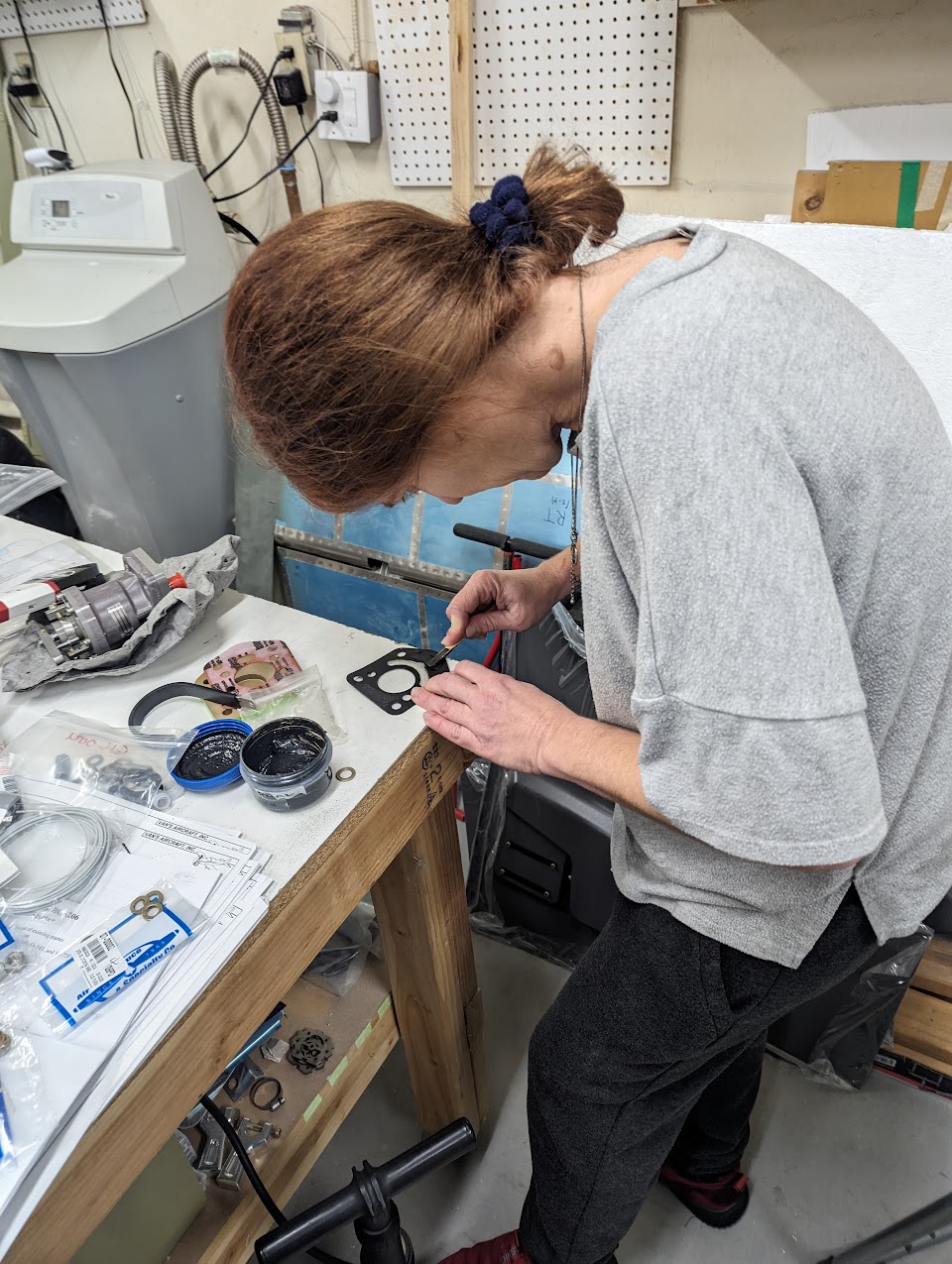
Last but not least, we attached the governor, using the gasket and N25-66 sealant (special thanks to Bobby Hubbard who sent me some sealant so I didn't have to buy a whole can!! :) ):
 |
| Applying Neil sealant to the governor gasket |
Only after it was in place and ready to be secured with washers and nuts did we notice that the studs are actually too long! That means the nuts wouldn't even reach the washers:
 |
| Governor attachment stud with threads not reaching its base |
Not wanting to waste the gasket/sealant, I added 5 washers and torqued it so the sealant got compressed the right amount, and I'll replace those washers (one stud at a time) when I figure out what to replace them with:
 |
| Governor attached to the engine (for now, with many washers) |
Main things left on the FF1 section are securing all the above items properly, and then the heat valve cables.
Time lapse:
Total engine installation rivets: 63
Total engine installation time: 20.8h
No comments:
Post a Comment