To get started on the finish kit, we started section 46, with the main landing gear.
I started by figuring out how to mount the Beringer brakes, since their manual leaves much to be desired (plus there are two versions of the manual, and they contain different information!).
I started by using a reamer to enlarge the holes that match the Beringer spacer, put a bolt through those for position, then match-drilled the 4th hole:
Match-drilled Beringer spacer hole
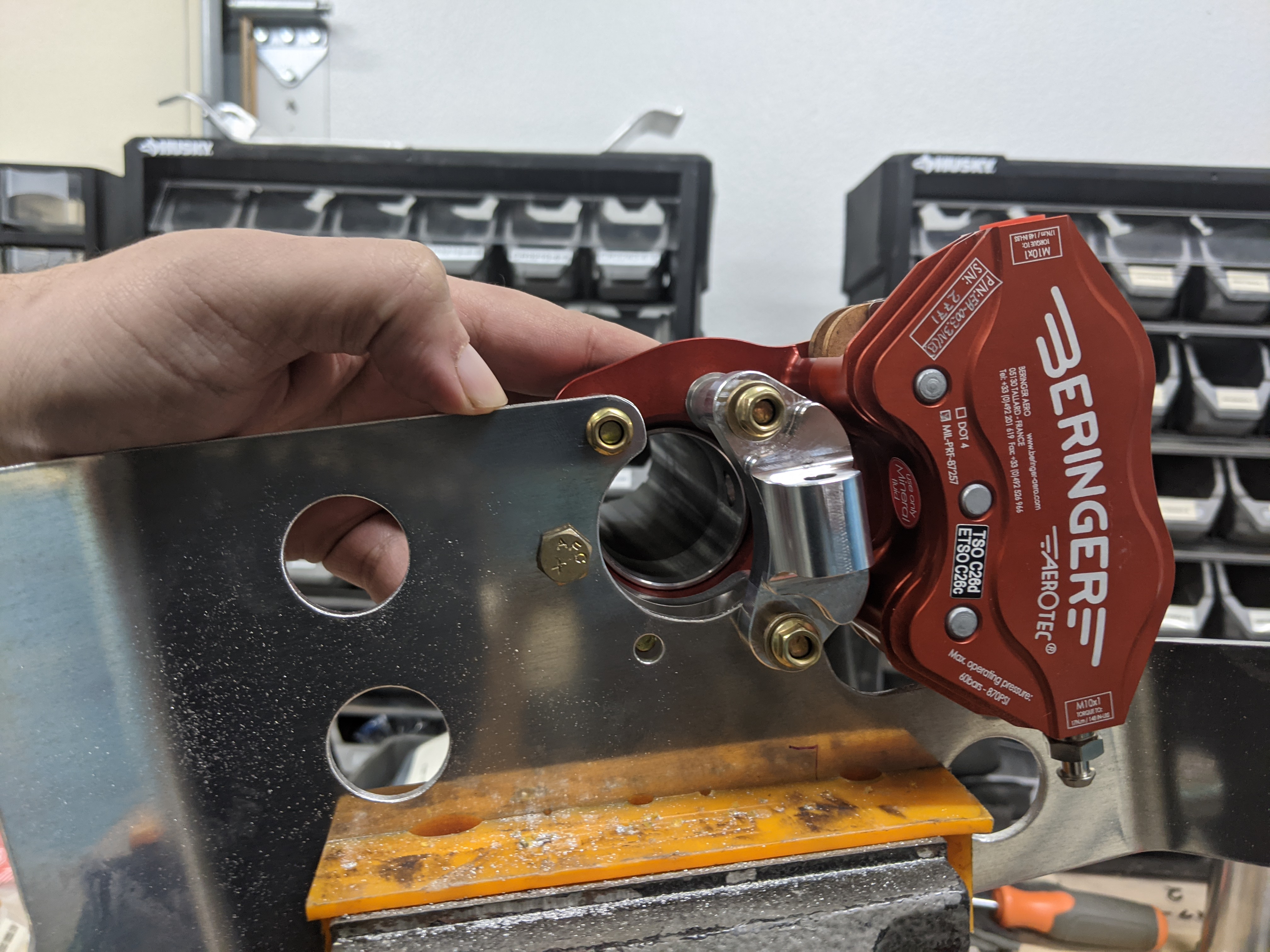
The axle is aligned by a small lip in the inner surface that fits through the brake, and bushings make the bolts be positioned with some accuracy:
Beringer brake and wheel mount showing bushings
The whole thing then gets attached to that spacer, and the wheel fairing bracket:
Beringer brake, wheel mount and spacer
Beringer brake attachment to spacer
making the final assembly look like this (I'll tighten mine only after that bracket is done and primed):
Beringer brake and wheel mount assembly (not tightened yet)
I also added the Flyboy jack points, which actually fit well with the Beringer, requiring just longer bolts (which they provided after I said I was installing with the Beringer) and an extra washer:
Brake mounting before adding jack point attachment
Side view of jack point attachment
Bottom view of the jack point attachment, showing extra washer in place
Side (and upside-down) view of the jack point attachment
I then reamed the holes for the pin that attaches the Beringer bracket (the original plans call for a bolt through these, but Beringer uses a pin which is held in place by the wheel itself):
Attachment pin going through Beringer mount and gear leg after reaming
Attachment pin going through landing gear leg after reaming
We then went on to attach the landing gear legs, which were a major pain - for one, priming the inside of the gear mount was a big mistake, but even after removing that primer, it still fits very tighly, and took a lot of rotating back and forth with a lever and even a bit of help from our friend the rubber mallet:
Using a lever to rotate the landing gear leg into place
Landing gear leg in place
With that in place, I followed the instructions to final-drill the attachment hole - first to 19/64", then to the recommended 0.311" (7.9mm), which fits the bolt extremely tightly:
Landing gear mounts with legs in place
Ready to final-drill gear leg attachment hole
Attachment bolt is very tight in this hole
Removing them was, again, no easy feat, and I'm eager to put on the wheel bearing grease on the surfaces before final attachment, as that will make it a lot easier. The whole process left some scratches on the gear right leg, which (after checking with Van's) I had to smooth out:
Scratches on gear leg from fitting it
After sanding that, and applying a good amount of grease, we installed the gear legs for good (the grease made it so much easier!):
Final-installed main gear leg
Main gear leg bolt torqued into place
After deburring and a primer session (shared with other sections), it was time to final-install the wheels and brakes:
Primed parts, including the gear mounting brackets
I'm using the Cleaveland/Aircraft Specialty axle extensions, so I enlarged the hole in the Beringer axle nuts and installed those, drilling through the bolt to install the cotter pin:
Axle nuts with the Cleaveland axle extensions
Finally, with all this, it was time to start installing it all:
Gear/brake parts ready for mounting
Along the way, we realized that the jack point can only be installed after the brakes are in place, otherwise it leaves no room for the gear leg to go in:
Jack point gets in the way of the gear leg if mounted before installing
There was also some interference between the mount bracket and the gear leg which had to be trimmed away and re-primed:
Interference where the brake mount bracket hits the gear leg
After those corrections, we assembled the brakes and wheels/tires onto the landing gear for good:
Installed brake and wheel axle
Installed brake and jack point
Installed wheels and tired on both sides
As a last snag, the cotter pins that are supposed to secure the axle nuts were too thick for the pre-drilled holes, so I had to final-drill them larger. Beringer uses part number L-V-005, which in one of the versions of their manual I found out is a 3.2mm (about 1/8") x 71mm pin (hole size 0.141"), but the cotter pin included with the Cleaveland axle was a bit smaller (7/64", hole size 1/8"), so I went with that smaller one.
As for the rest of this section, both the engine mount and nose wheel are on hold until I order the engine, since Barret needs to modify the engine mount for their cold-air induction.


No comments:
Post a Comment