If you thought that I was done sanding the doors, you were wrong :)
To adjust the gap between the doors and the cabin cover, I used a .032" strip as a "feeler gauge" to sand the edges until it passed, then ran the Dremel cutter disk (which is about .04" thick) through it - that gave me a nice uniform gap all around (except in a few spots where the gap was already larger):
"Gauge" for judging the door gap
Uniform gap between the door and the cabin cover
I was worried that the edges of the doors are already kinda thin, so I instead preferred to sand down the cabin cover edges, since those are pretty thick:
Sanded-down cabin cover edges to adjust gap to the doors
I also countersunk the screw holes for the gas strut attach bracket:
Countersunk gas strut attach bracket holes
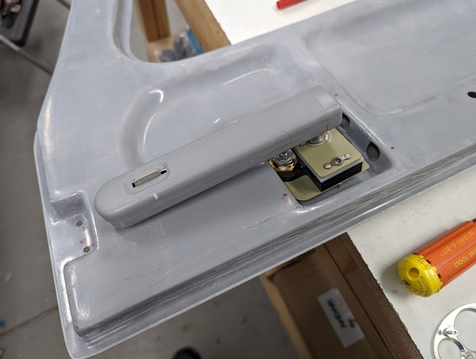
Next, I disassembled all the door mechanisms - latch/lock, hinges, etc. to prepare it for painting. I took the opportunity to attach the Aerosport handle covers:
Aerosport door handle cover in place
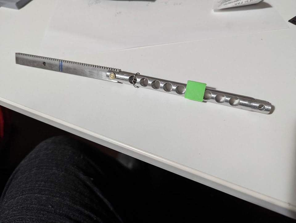
I also decided to use that extra hole on the door (the one that's used for attaching and safety-wiring the pin) for an analog "door latched" indicator, which I printed with ABS:
Door pushrod with latching indicator installed
3D printed door latch indicator
Door "indicator hole" showing green when the door is latched
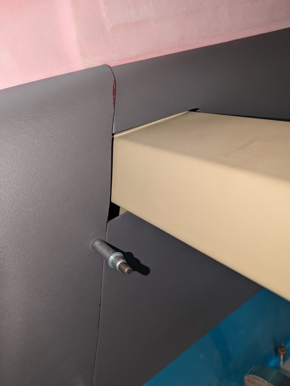
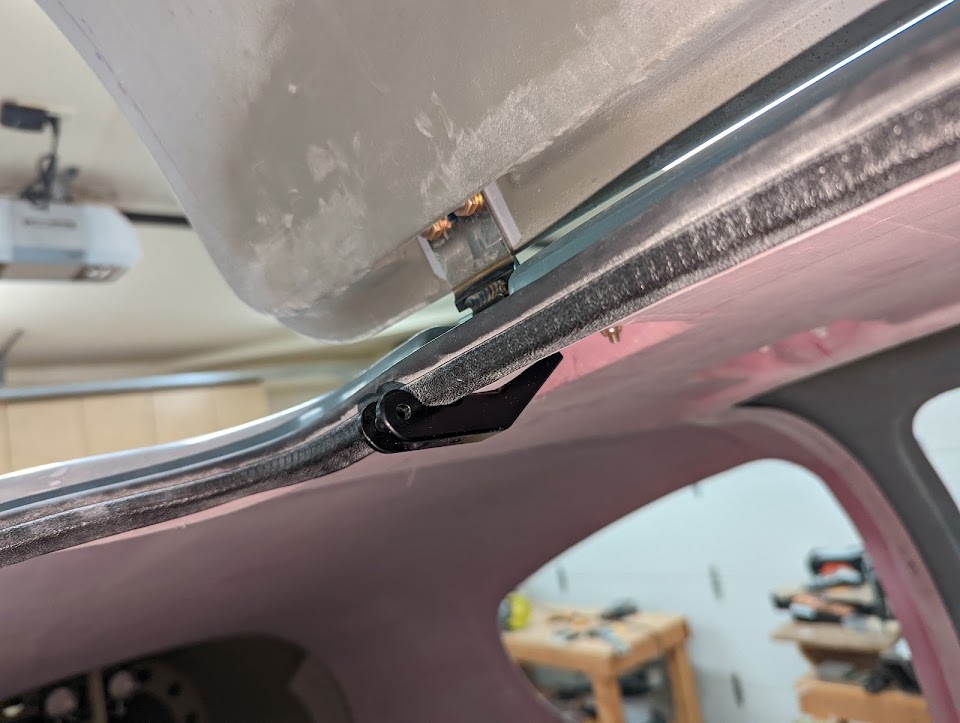
After removing the cabin cover, I opened up holes on the sides of the overhead console to fit the gas strut attach brackets:
Gas strut attach bracket coming out through hole in the overhead console
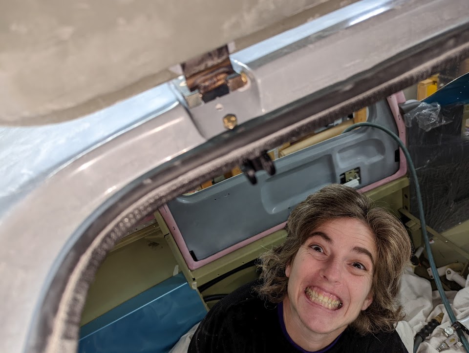
Overhead console with gas strut attach brackets sticking out
I sanded the inside of the hinge pockets for the reinforcement plates, and trimmed the corner of one of the gas strut attach brackets so it wouldn't interfere with the reinforcement plate:
Interference between left gas strut attach bracket and door hinge reinforcement plate
Gas strut attach bracket with a corner removed
We then permanently attached the reinforcements with epoxy/flox (with the screws secured in place to ensure alignment and keeping the resin out of the holes), and built up underneath the gas strut attach brackets to give a solid surface for it to rest against:
Door hinge reinforcement plates glasses into place
Gas strut attach bracket and door hinge reinforcement plate
Gas strut attach bracket surface on the cabin cover, next to the door hinge reinforcement plate
All but one of the screws came off easily - that one that didn't, of course, got stripped and took over an hour to remove, and I ended up drilling/breaking its head off then unscrewing it on the vise:
Removing the stripped screw from the gas strut attach bracket
Luckily, the threads on the bracket seem undamaged.
Next for the doors is finishing and painting the inside surface, then putting all the parts back together, but first there's a ton of work to do on the cabin cover.
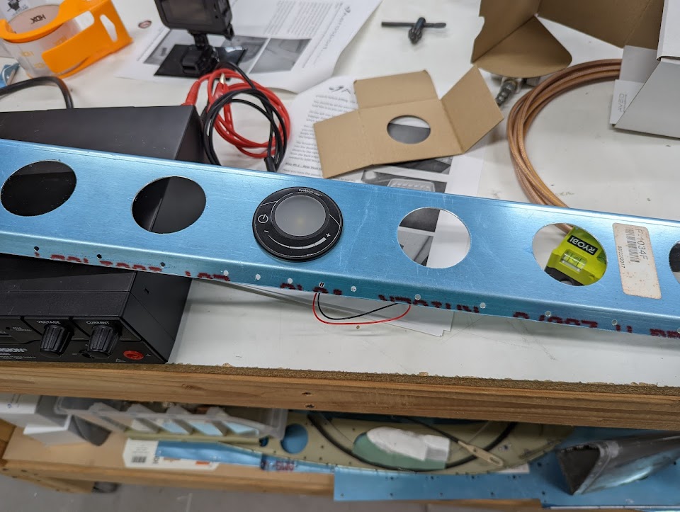
I got my interior lights from Aveo, and verified that their Dome does fit well in the seat back brace closeout:
Aveo Dome light attached to a hole of the seat back brace closeout
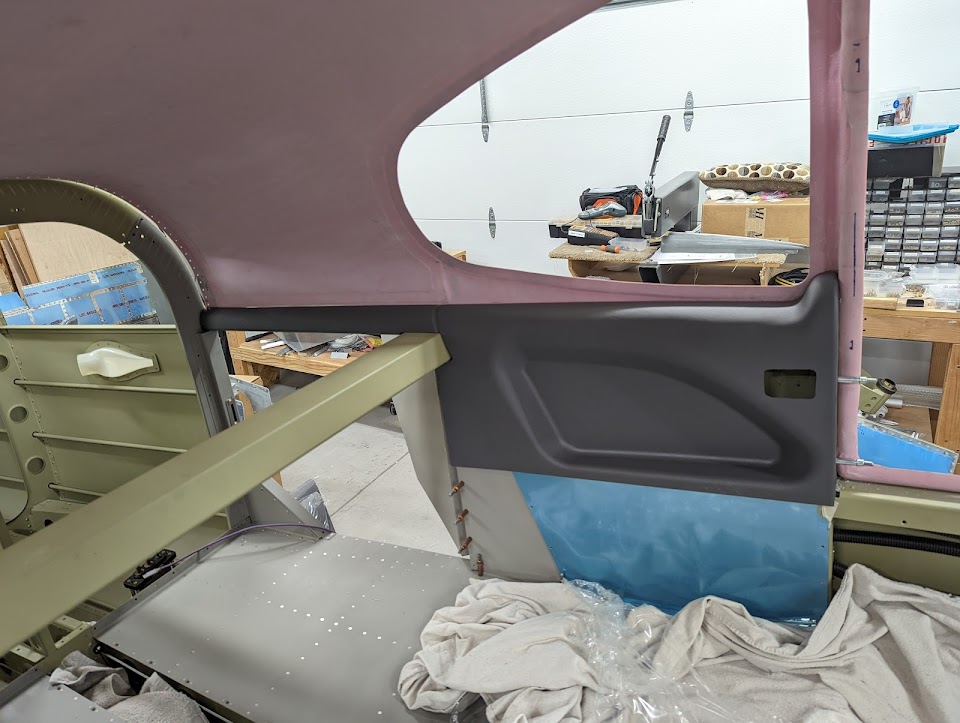
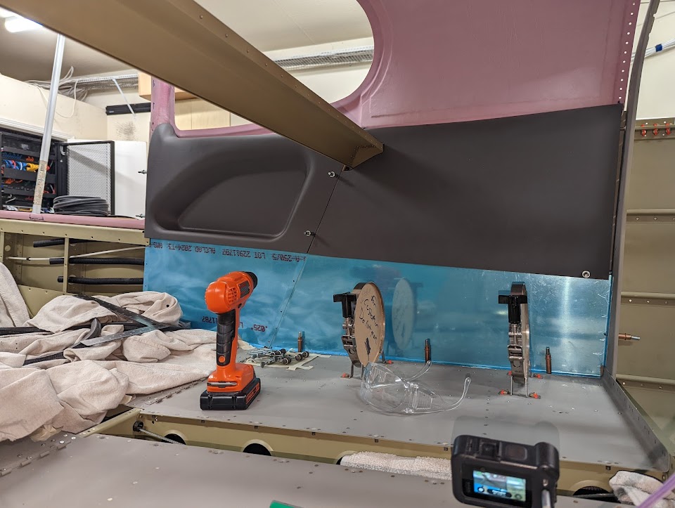
I also got my interior panels from Aerosport, and started the process of fitting and attaching them. They get attached by surprisingly few screws (some of them going through the longeron), but once that's done they actually feel pretty firm.
Left rear and baggage panels in place
While it's true that there's not a lot of trimming to be done on these parts in terms of dimensions, the little trimming that's required needs to be done very slowly since there's no way to add back material if one removes too much, plus it takes some fiddling to adjust their alignment among themselves and with the airplane structure - for one, because plastic is flexible so they align a bit differently depending on how you hold them. After a lot of small adjustments, I got a pretty good fit:
Overlapping joint between the right rear and right baggage interior panels
Right interior panels attached in place after trimming
I still need to attach some of the nutplates for these panels (which will be easier to do once the cabin cover is off again), and haven't started work on the front panels yet, but the rear and baggage panels are done.
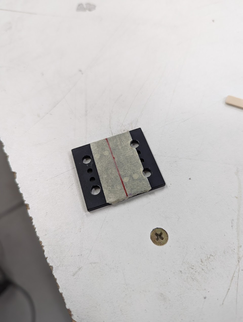
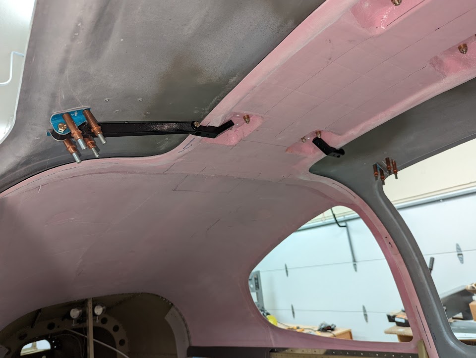
We finally got around to attaching the gas strut brackets. To line them up, we used a center line through the hinge reinforcement plate, since that aligns with the hinge screws. We had to use the original Vans bracket for drilling (since the PlaneAround brackets are tapped).
Reinforcement plate with a centerline marking for aligning the gas strut attach bracket
Marking the exact alignment of the gas strut attach bracket
Gas strut attach bracket in place with the McMaster seal
Gas strut attach bracket successfully installed and fits the McMaster Seal!
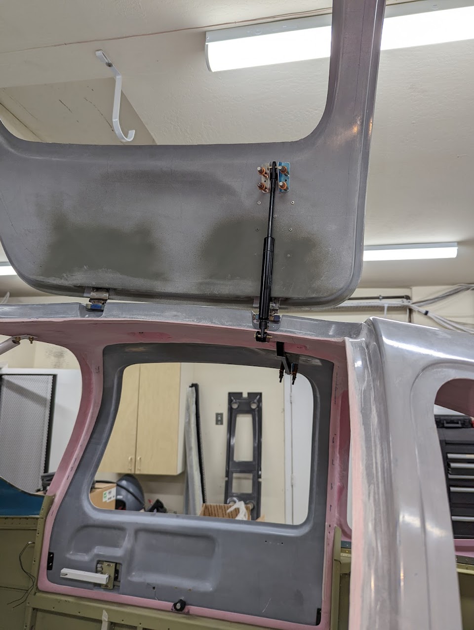
Gas strut mockup
Door held open by gas strut
I also finished riveting the hinge reinforcement plate nutplates:
Door hinge reinforcement plates with nutplates riveted to them
and trimmed the Aerosport latch cover (since for some reason, they didn't design it to fit with their own handle kit?):
Aerosport latch cover trimmed for their low-profile handle kit
Next I plan to adjust the gaps around the doors, then the cabin cover can finally come off one last time for finishing.
After detaching the rudder and vertical stabilizer (hopefully for the last time before final assembly), I started to comply with SB 18-03-30. As previously mentioned, the elevators were at the high end of the required travel range (at 30˚ up, with the required range between 25˚-30˚), but at that position they weren't being stopped by the flanges of the horns, making compliance required:
Filed-down elevator stop angle in an attempt to comply with the SB
I measured, and if only the elevator stop angles hadn't been filed down to give the full range, then the horns would still touch them at the flange, and the movement would only be down to 28˚ up, still within the allowed range, so I removed the elevator stop angle and replaced it with a new but equal (just unfiled) part:
Removing the elevator stop angle
New unfiled elevator stop angle clecoed in place
New elevator stop angle riveted in place
I also opened up a bit of the rudder's leading edge to give room for the grounding strap without interfering with the attachment:
Grounding strap hidden behind the leading edge
Leading edge after removing additional material
New leading edge gap exposing the ground strap attachment point
Grounding strap attached to the rudder
Finally, I 3D printed the template to adjust the elevator pushrods:
3D printed elevator pushrod template with holes for clamping
Elevator pushrod template clamped in place
With this, the last steps on section 11 are now left for the final assembly at the airport.
Ok, if I said that section 32 was complete before, I lied: there were two dimpling steps left - the top tailcone bulkhead and the corresponding skin holes - which are now also done.
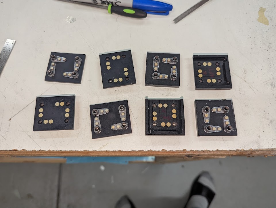
I epoxied the magnets inside the door latch pins (and later carefully cleaned up the threads):
Door latch pins with magnets epoxied inside
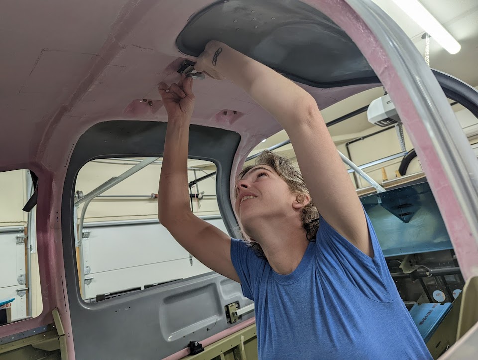
I had to try a few different sensor positions to get the right sensitivity - in the end, attaching to the top screw worked well:
Attempted reed sensor position that didn't work
Reed sensor position that worked properly
Testing the door sensor
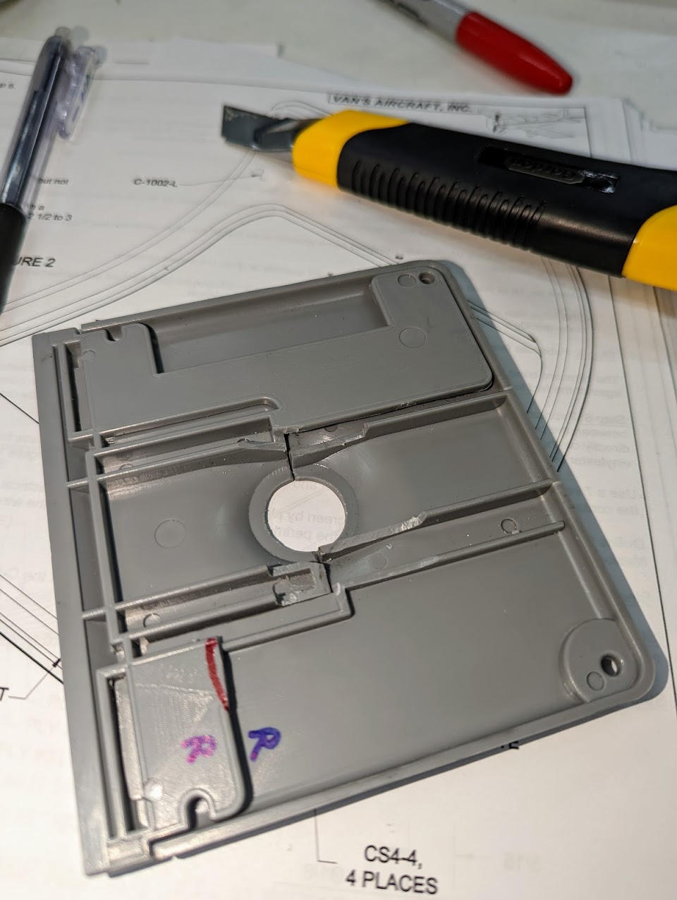
I then started the work to close up the hinge pockets, so that the McMaster seal can seal that part of the door. I made 4-layer fiber "plaques", trimmed them to fit just slightly inside the hinge pockets, then attached them with two more layers underneath (grabbing the sides of the pockets), and two layers on top (to make a smooth transition, and also to follow the cranial cavity curve):
Laying up a flat plaque for closing the door hinge pockets
Sanded hinge pockets for attaching the covers
Hinge pocket cover plaques marked up for trimming
Hinge pocket cover plaque held in place
Hinge pocket cover plaque held in place
I used some 2x4s (on top of peel ply) to keep the layup on the same plane as the original door surface:
2x4 block "press" to keep hinge pocket covers flat with door surface
Hinge pocket cover fiber layup inside the pockets
Hinge cover layup in place
After a lot of sanding and filling to make it smooth again, I applied a coat of primer, and this is now ready to fit back:
Hinge pocket covers after sanding
Filling holes in the hinge pocket covers
Hinge pocket covers with primer applied
With this done, I can finish fitting the McMaster seal, position the gas strut bracket and drill the door to attach it.
We finished filling and sanding the rudder fairings and their gaps:
Bottom rudder fairing with a huge gap to the rudder
Bottom rudder fairing after a lot of filling and sanding
Top rudder fairing after filling and sanding
and finally covered them with primer (which I have to say ended up being less smooth than the sanded surface :) but it's only temporary until paint anyway):
Top rudder fairing with primer applied
Bottom rudder fairing with primer applied
The only empennage fairing left now is the top VS fairing, which has a huge gap to be filled in the forward portion.
Section 20, Bottom wing skins, is finally complete! It mostly went smoothly, and I even managed to do a lot of it solo this time, partly by riveting all but the last bay top-to-bottom rather than leaving the last 3 bays for later. The last bay is pretty easy to reach (compared to the others) through the rib holes.
Completed right wing
While technically part of this section, I'm not actually attaching the pitot tube now - I'll leave that out until after the wing is attached to the fuselage to make it easier to handle.